Team Members
- Carter G Bordeleau
- Ali Choudhry
- Mahmud Jumaev
- Mustafa A Siddiqui
Mentors
Professor Jack Mottley and Professor Daniel Phinney
Our Goals and Endeavors
The purpose of this project is to design an inexpensive solar tracking system where the installation process has been facilitated, allowing for the apparatus to be accessible to individuals who lack knowledge and skills related to the project’s design. In other terms, the solar tracking system should be uncomplicated to install and use. Additionally, we endeavor to fo
The purpose of this project is to design an inexpensive solar tracking system where the installation process has been facilitated, allowing for the apparatus to be accessible to other individuals. In other terms, the solar tracking system should be uncomplicated to install and use. Additionally, we endeavor to follow a systematic approach where the system’s power intake exceeds that of conventional solar panels and alike systems. The solar tracking system should suffice as a suitable replacement for stationary solar panels, optimizing power absorption.
This is accomplished utilizing varying sensors including an accelerometer, magnetometer, and GPS module. Additionally, we utilize a Microcontroller for the main computing and logic, and gearmotors to move the solar system. Finally, we install four reflectors that reflect sunlight into the solar panel itself, significantly increasing energy absorption.
In essence, we strive to create a tool capable of producing more environmentally-friendly and green energy, which at the same time, is more capable than other methods of producing energy, such as a fossil fuels. With the increasing amount of pollution in our world, we believe this project is a step in the right direction to make our world a cleaner and more sustainable place. (Interestingly enough, this project can also be used to power moon rovers, as the reflectors would allow for much higher energy absorption).
Hardware Design
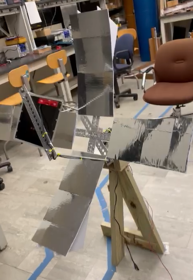
- Aside from the wooden stand and metal bearings that hold the entire system together, a crucial component in our project is the reflectors. By re-directing sunlight from four separate areas into the solar panel, we are able to increase the overall effiecieny and power absorption of the solar system.
- Software Design
- This is the area where all the main controls, logic, and functionality of our project takes place. First, and arguably the most important component utilized in our software, is the microcontroller. This behaves as the central computer for our project. Next are our three sensors: the Accelerometer, Magnetometer, and GPS. With these three devices combined, were are able to determine the current position of the sun, and can tell the solar system which direction to move in order to align itself with the sun. Lastly, we have our motors. We utilize two motors in our project. One motor rotates the solar system in a horizontal direction, while the other does so in the vertical direction. Combined, the two motors allow us to position our solar system towards the sun.
- Our Sensors, Devices, and Central Computer:
- Accelerometer
- This device determines the proper acceleration of the system. In other terms, this sensor detects detects the current motion of the solar system in the X, Y, and Z directions.
- With this information provided to use by the accelerometer, we are able to calculate the current zenith angle for our device — the angle between our device and the vertical axis. Once this is angle is determined, we can tell the motors how high or low it needs to position itself for the solar system to face the sun.
- Magnetometer
- This device is capable of measuring the magnetic field in the X, Y, and Z directions in respect to the sensor’s current location. In other terms, we are able to determine the magnetic intensity in each direction with the use of this sensor.
- When we place this sensor flat, we can completely disregard the Z-direction measurement and consider only the X and Y measurements. These two measurements allow us to use the sensor as a compass, and determine which direction is North. With this information, we are able to calculate our current azimuth angle — the angle between our device and the Earth’s North. Once this is angle is determined, we can tell the motors how much to horizontally rotate to position the solar system towards the sun.
- Global Positioning System Module (GPS)
- By communicating with local satellites, the GPS module allows us to determine our current longitude and latitude coordinates, as well as the current date and time of day.
- With this information, we are able to calculate the current azimuth and zenith angles of the sun. Once these have been calculated, we move both motors until the calculated azimuth and zenith angles from the accelerometer and magnetometer match that of the GPS.
- Motor Control
- In this project, we utilize two separate motors: one for horizontal-based movement, and the other for vertical-based movement. The vertical-direction motors moves according to the accelerometer’s data, while the horizontal-direction motor moves according to the magnetometer’s data.
- Each motor is connected to an H-Bridge circuit. This circuit determines how fast the motors will rotate, and which direction the motors will rotate. As a result, this device facilitates the control of our motors.
- Microcontroller
- The microcontroller behaves as the central computer of our overall system. The ‘brains’ of the project if you will. All measurements determined from our sensors are sent to this device, which are then used by the microcontroller to undergo all the appropriate calculations.
- Additionally, the microcontroller sends the appropriate instructions to the H-Bridges and Motors allowing for the motors to move, and then tells them to stop moving once they have reached the appropriate position.
- Accelerometer
- Methods of Communication Between Devices
- This section describes how the different sensors and devices in our project communicate with each other. Here, we will talk about some core topics related to Electrical Engineering. If you are unfamiliar with these topics, feel free to move to the next section
- One method of communication we have instated into our project is the Universal Asynchronous Receiver-Transmitter Protocol (UART). This method allows for asynchronous communication between two devices. In our project, this occurs between the GPS Module and the Microcontroller. Both devices send and receive data to each other at separate times. Generally, a microcontroller would send initialization commands to the sensor it is communication with for proper utilization. Luckily for us, the GPS does not require such commands. As a result, after starting up, the GPS automatically sends data to the Microcontroller, allowing for us to store this information into a UART buffer and use it for our calculations.
- The second method of communication we utilize is the Serial Peripheral Interface Protocol (SPI). This is a synchronous method of communication that allows for the sending and receiving of information at the same time. In this protocol, four specific pins of the microcontroller are needed; System Clock (SCL), Serial Data Out (SDO), Serial Data In (SDI), and Chip Select (CS). The SCL pin determines at which frequency information will be transferred between devices, while the SDO and SDI pins transmit and receive data between devices. These three pins are shared between the microcontroller and all other devices undergoing SPI. The CS pin refers to which specific device the microcontroller is currently communication with, meaning each separate device is connected to a separate CS pin. In our project, the Magnetometer and Accelerometer communicate via the SPI protocol with the Microcontroller.
- Our final method of communication is the simple Digital Input/Output interface. This method simply sends an electrical pulse from the microcontroller, signifying data transmit. This method, often referred to as Pulse Width Modulation (PWM), is utilized to send data to the H-Bridges of the gearmotors.
Module Diagram
Our software is divided into the following modules. In the codebase, one can see files for motor control, accelerometer and magnetometer device drivers, GPS sensor driver, communication protocols (UART and SPI), and PWM. All this comes together in our main function to move our system as desired.

Our Results
- We are able to observe 300% more power output with our system as compared to a standard stationary solar panel.

- What’s inside our Fuse Box?
- Inside this neat little box, you will discover a meter, which measures the voltage, current, power, and energy our solar panel is absorbing. This helps us to ensure everything is function as intended.
- Additionally, you will find a PCB board consisting our our main circuitry for our project. Most importantly, this board hosts the microcontroller, which is the main computer and processing unit of our project. Additionally, you will find an LED, which lights up during the initialization process and then turns off when it is finished. This allows us to ensure all modules are functioning at startup, and if something were to go wrong, the LED would keep on flashing until the user cuts the power.
- Schematic of our Design
- For those who may be interested, this is a breadboard schematic of our project design. It indicates how all the wiring is done, and which pins of the Microcontroller each device and sensor is connected to.

- List of all Components Used in our Project
- PIC18F4680 Microcontroller
- PICKIT3 Programming Tool
- Adafruit LIS2MDL Magnetometer
- Adafruit ADXL343 Accelerometer
- NEO-6M GPS Module
- BRINGSMART 12V 12RPM 70Kg cm DC Worm Gear Motor
- DRV8801 Single Brushed DC Motor Driver Carrier
- R-78W5.0-0.5 12V to 5V DC Converter
- Weize YTX4L-BS Battery
- ECO-WORTHY 12 Volt 5 Watt Solar Panel
- If you are interested in our code and want some insight to our developmental process, here is a link to our GitHub Repository which contains all of our code, documented progress, and any materials we referenced to write the code including datasheets.