Problem Statement
The use of surgical loupes with a fixed angle of declination is not optimal for all types of surgeries and is a contributing factor to musculoskeletal discomfort in surgeons due to constant posture readjustment during operations. We aim to create an attachment that can allow the user to change the declination angle and improve overall posture during long hours of operations.
Background and Customers Scenario
Background
Surgical Loupes are class I medical devices that are used by surgeons and dentists to magnify their field of work. Two of the common types of surgical loupes are flip-up loupes and Through-the-lens (TTL) loupes. The barrels of TTL loupes containing the magnifying lenses are fixed at a specific angle to improve the user’s ergonomics during long procedures. Unfortunately, the fixed angle of declination is not fit for all types of surgeries, such as one of the surgeries carried out by our customer.
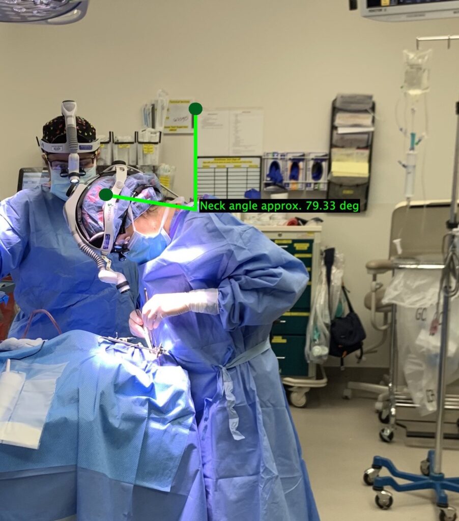
Our customer is Dr. Sarah Neimanis, a plastic surgeon at Strong Memorial Hospital. One of the surgeries our customer performs are cleft palate repair surgeries on infants and children. To clearly visualize her surgical field, our customers has to bend her neck in an uncomfortable position because the fixed declination angle of her loupe, 20 to 30 degrees, is not suitable for cleft palate surgeries. As shown on the picture on the left, our customer’s neck is bend at angle of approximately 79.33 ± 2.97 degrees, measured with ImageJ. In general the recommended head tilt for a comfortable posture during surgery is equal to or less than 20 degrees. Therefore, in our customer’s case, she is 50-60 degrees off of the safe head tilt angle, which result in discomfort during cleft palate surgeries over prolonged periods.
Customer Scenario
1. PURCHASING AND AQUIRING SURGICAL LOUPES
Surgical loupes are custom made to fit the end user. Surgical loupe manufacturers, such as Design for Vision and Orascoptic, take measurements of the intended user’s inter-pupillary distance and working distance. Furthermore, the magnification is taken in to consideration, since it varies with surgery types. For instance our customer’s surgical loupes have a 2.5X magnification.
2. Operating room (O.R)
Before the surgery, the surgeons prep the patient and the table in the operating room. The surgeons then puts on their surgical gear and make sure everything field is sterilized. They bring in their loupes in cases then put them on before surgery. They do not need to sterilizes the loupes every operation because they loupes do not come in contact with the patient. The surgeons will then turn on the lights and put on a headlamp to be able to clearly see the field of operation.
In the O.R. there is also a bench over which the patient lies. For cleft palate surgeries, the surgeon usually stands at the end of the bench, behind the patient’s head. Given the steep angle at which the surgeons has to work at for cleft palate surgeries, the height of the bench can be adjusted and in some cases the bench can be tilted at a very small angle.
The adjustable bench together with the fixed declination angle of the loupes are meant to make the cleft palate surgical field more accessible and improve the surgeons posture. However, as shown in the image above, this does not accommodate for the extra degrees of declination needed in this surgery and the surgeons ends up compensate for this with poor posture and a higher head angle of declination.
3. oPERATING LOCATIONS
It is common for surgeons to have mission trips to different countries to perform surgeries. This is the case for our customer who is primarily based in the U.S. but does mission trips in South America to perform cleft palate surgeries back to back for a week or however long they are traveling. In these settings, surgeons including our customer, typically carry their surgical loupes, mostly because they are custom made for them.
4. How does our Device fit in the customer scenario?
Our device will function as removable attachment to existing standard surgical loupes that enables the user to change the angle of declination. This would enable better posture and reduce neck and back for the surgeon performing surgeries such as cleft palate surgeries, that require a declination angle greater than the fixed 20-30 degrees of loupes.
Before surgery, the surgeon would attach the device to their loupes, adjust the declination angle as desired, put on the loupes, and adjust the table to the height that gives them as much comfort as possible. The loupes with the attachment would be used continuously through the entire surgery. After the operation, the surgeon would be able to remove the device when the surgical loupes are taken off.
Design Concept and Prototyping
Design Concept
The device was designed with the intent to meet the customers needs and wants. The primary of our customer needs included 1) having an adjustment method for the angle of declination, 2) keeping the magnification unchanged, and 3) having a secure and stable attachment mechanism to the surgical loupes. Our approach to solving the problem at hand consisted of analyzing each need one at a time and determining a solution that meets the specific need.
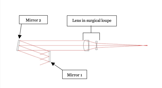
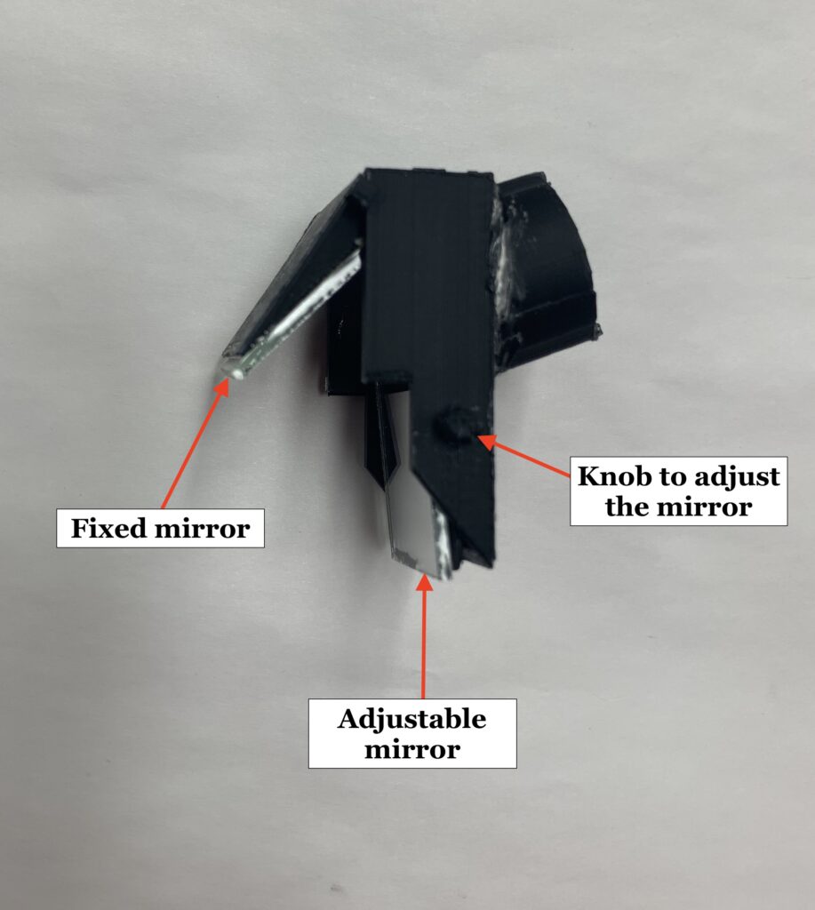
Our design is based on the concept of light reflection on mirrors. We decided to use two mirrors, opposite to each other and misaligned vertically, to manipulate the angle at which light enters through the loupes. In the diagram below Mirror 1 that is on the optical axis, of the loupes barrel containing the lenses, is fixed a small angle while Mirror 2, that is below the optical axis, is adjustable. Having an adjustable mirrors allows the user to change the declination angle as needed. The position of the mirrors dictated the rest of the design, which include the housing of the device and possible adjustment and fastening methods. A number of prototypes were built with the goal to maximize the field of view seen with the device on, optimize comfort when using the device, and ensure secure fastening of the device on the surgical loupes.
Prototyping process
Our first and second prototypes were made with cardboard, mirrors, and a screw. These prototype were used to assess whether the design concept we choose solved the problem and met the needs and wants provided by our customer. The third and fourth prototypes were 3D printed and fit to the surgical loupes for testing.
First Prototype
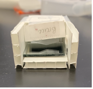
The first prototype was made of cardboard for the housing, two mirrors, and a screw for adjusting one of the mirrors. This prototype proved proved that using two mirrors allows the user to change the angle of declination.
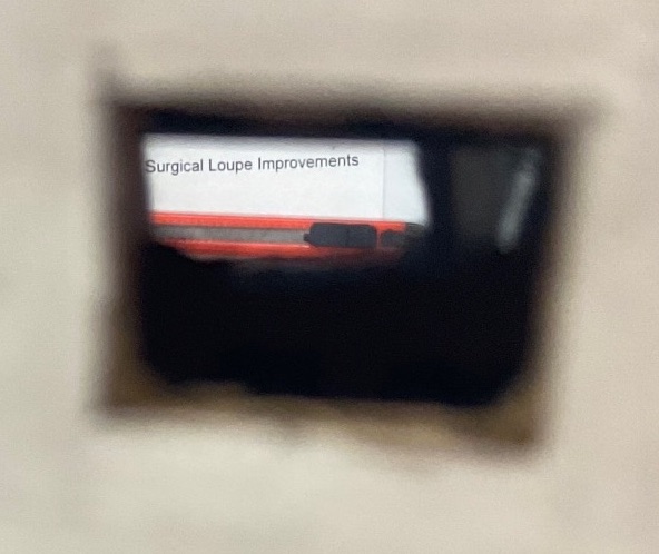
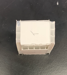
The images below shows the inside of the prototype with the two mirrors (image 1), the prototype viewed from the outside( image 2), and the bottom of the prototype where a rectangular hole was cut to allow a limited amount of light inside the device (image 3).
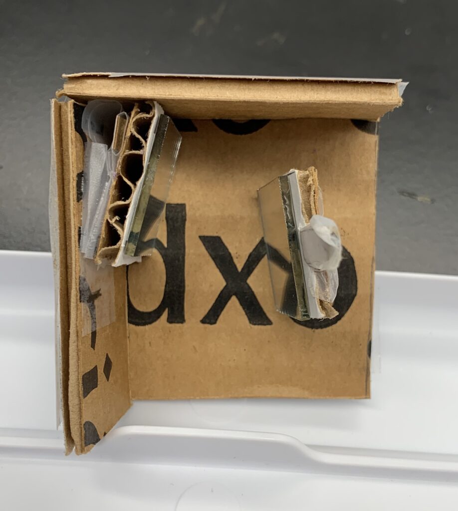
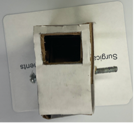
Notes on prototype 1: As mentioned above, the bottom of the box was covered/closed and had a small rectangular opening. Having a closed bottom with a small window greatly reduced the Field of view.
Second Prototype
The second prototype was similar to the first prototype with two significant modifications. The first modification was made to reduce the size of prototype by decreasing the distance between the two mirrors bringing the fixed mirror closer to the loupe’s barrel. The second modification involved leaving the bottom of the prototype open to increase the field of view.
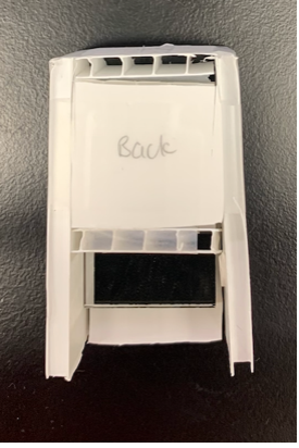
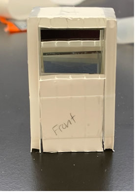
Notes on prototype 2: The second prototype provided a larger field of view and was more compact than the first prototype. The design above was used as base for building the third prototype that was 3D printed.
Third Prototype
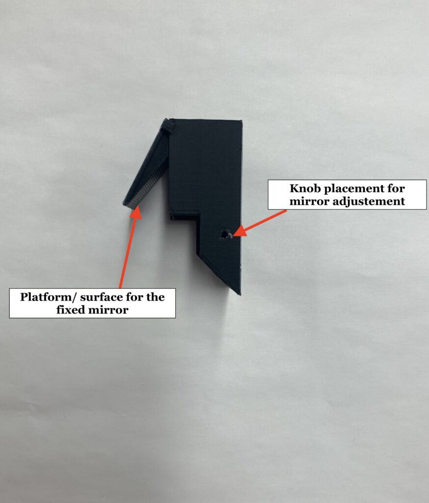
The third prototype was designed using the Onshape computer software and had a design similar to prototype 2. While making designing CAD model of third prototype, we noted having the fixed mirror inside a compact device could pose a problem when it came to cleaning the mirror. Given this realization, the third prototype was designed with the goal of allowing easy access to both mirrors for cleaning purposes or even maintenance in the future.
From prototype 2, the movable mirror is already exposed, which gives an easy access for cleaning and repairing. For the fixed mirror, the platform or surface onto which the mirror is attached, in the third prototype, can be lifted upward in order to access the mirror without having to disassemble the whole device.
Notes on prototype 3: Though the prototype allowed the user to change the angle of declination, it was created discomfort when used with the loupes. Due to its straight and vertical surface, the attachment got in contact with the users face put pressure on it which created the discomfort.
Fourth Prototype
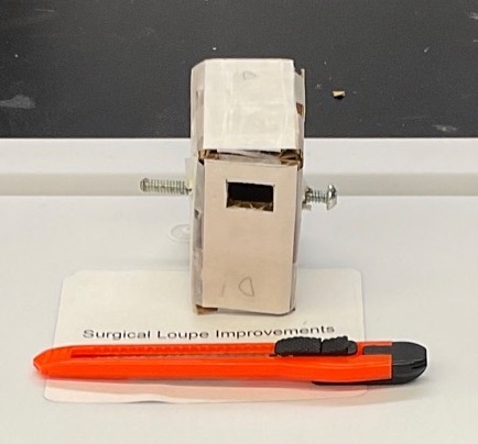
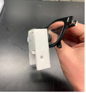
Due to the discomfort created with the attachment, a brace was designed for the fourth prototype. The brace acts as a connector that connects prototype 3 and the surgical loupes. The brace was designed with the idea of elevating the device to prevent contact with the users facial features. Furthermore, the brace can be designed in multiple shapes to fit the multitude of surgical loupes with different barrel shapes.
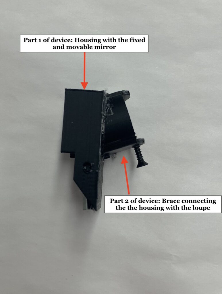
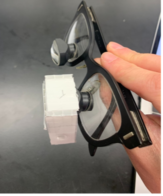
The brace and the device housing or box containing the mirrors were attached together, as shown above, to make prototype 4. This prototype was then duplicated to have two devices that could be added on the two barrels of the loupes, as shown below.
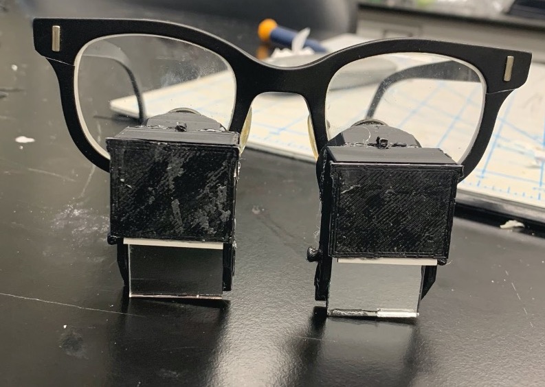
Notes on prototype 4: The brace is meant to fit tightly on the barrel of the loupes. However, due to the shape and the protruding part of the lens in the barrel, the attachment can be loose around the barrel which is why a screw is needed to fasten the device on. the loupes. Using a screw for fastening the device may lead to the appearance of scratches on the device over a long period. This can be mitigated with the use of padding at the point of contact.
Testing and Results
After building the fourth prototype, we performed several tests to determine the effect the device has on the surgical loupes. The test conducted included quantitative tests and qualitative tasks. The quantitative tests involved the measurement of the systems Modulation Transfer Function, Distortion, and changes in the field of view. The qualitative test involved volunteers who used the device and gave their opinions on the device.
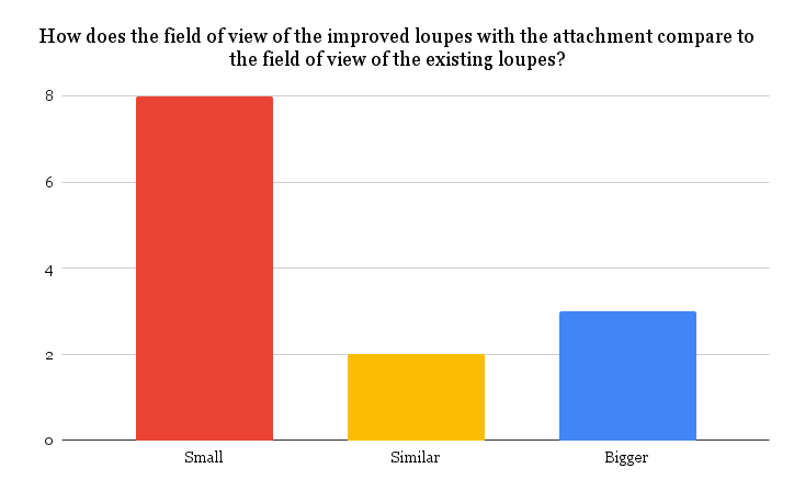
Field of View Test
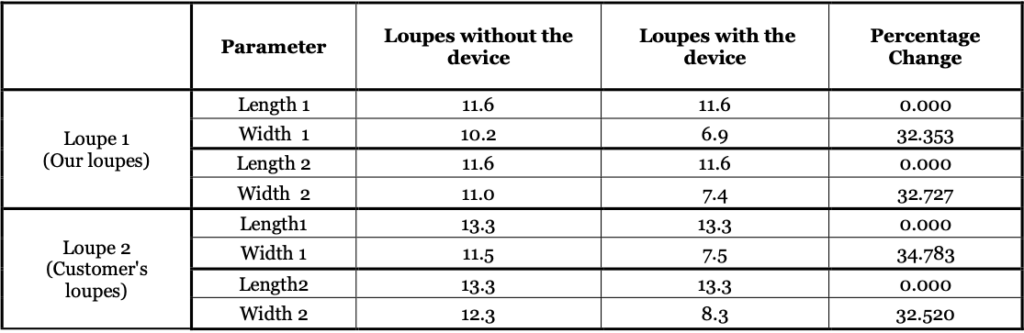
It was noted that the field of view (FOV) decreased when the device was used with the loupes. To determined the percentage decrease in FOV, the team used the device on two different pairs of loupes, one from our customer and the other from the team.. While wearing the loupes, the FOV of the loupes only was drawn on a piece of paper. Then the person taking the measurement added the final prototype to the loupes and drew the new FOV over the one previously drawn to observe any possible change.
For the first pair of loupe, the width of the FOV decreased by 32.353 % and 32.727% for the two measurements. The second pair of loupe belonging to our customer decreased by 32.520% and 34.783 % in width when using the device. The length of the FOV did not change in both cases.
Distortion Test
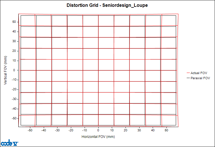
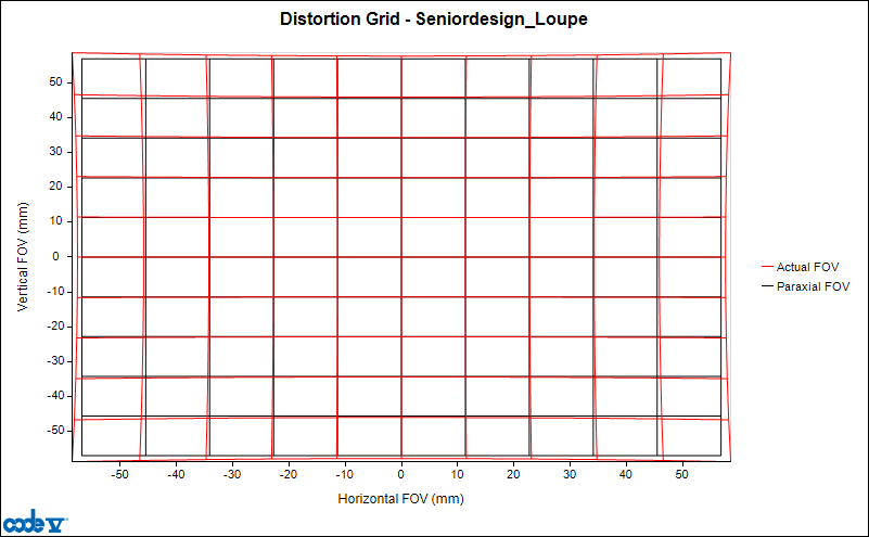
One of the goals for this project was to make a device that would change the angle fo declination without significantly altering the optical properties of the system. Therefore, it was important to test system properties, like the level of distortion, of the system with and without the device on to identify any major changes introduce by our device.
For the distortion test, the aim was to have a similar distortion percentage for the the loupes with and without the device. Unfortunately, we did not have the required information regarding the specifications of our customer’s loupes to conduct a distortion analysis in CodeV. Instead, a patent owned by the company that manufactured our customer’s loupes with all the necessary specification was used for the test. The results are presented in the table below.
| Surgical Loupes without the device | Surgical Loupes with the device | |
| Percentage distortion (%) | 2.867 ± 0.223 | 3.005 ± 0.005 |
Both systems had a pincushion distortion. It seems like there is no significant change in the distortion percentage, since the range of the distortion percentage for the loupes without device includes the percentage for the distortion observed in the system with the device.
Modulation Transfer Function Test
Similar to the distortion test, a modulation transfer function (MTF) test was performed to assess the performance of the two optical system to determine if there was any changes in the image quality (Edmund Optics, Introduction to modulation transfer function). The MTF of the system with the device resulted when the fixed mirror was fixed at an angle of 10 degrees and the movable mirror was at an angle of -20 degrees. The two MTF are similar to each other, indicating no significant change in the image quality.

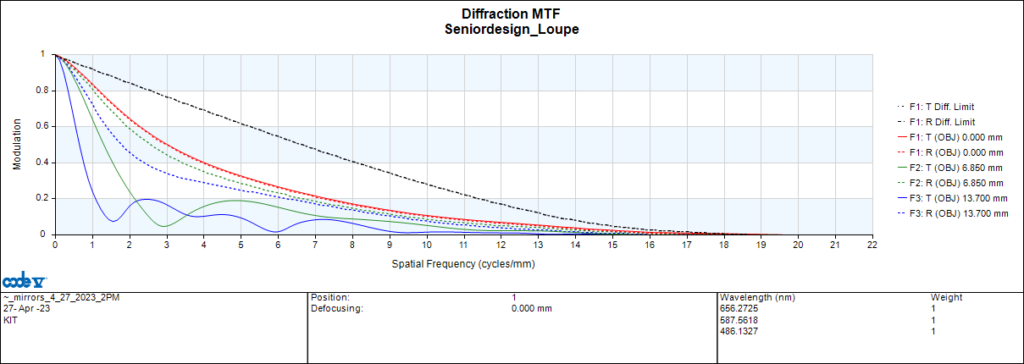
Note: It is important to note that, depending on the angles of the mirrors, there are some changes in the MTF. The most common change is due to vignetting which will lead to the disappearance of the blue curves. As vignetting increases the blue curves disappear, showing that the angles at which the mirrors are placed affects the final image.
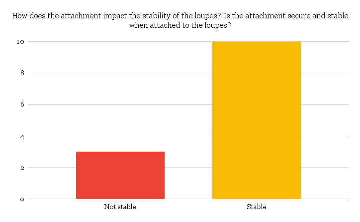
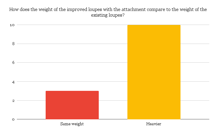
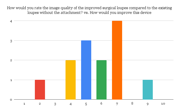
Qualitative Test
Thirteen students were asked to use the surgical loupes the team had with and without the device and provide feedback through a google form. The participants were asked to comment on the change in the FOV, the weight of the system with the device, and the image quality. The results are provide below.
Future Directions
1. MANUFACTURING
Currently, our device is still in its early stage as a prototype. We would like to look into manufacturing the device on a larger scale. Since there are different types of surgical loupes with different barrel shapes, barrel length, and materials, it might affect our ability of mass manufacturing the device. Therefore, our next step involves determining the type of material we would need to make the housing of the device and whether we need to use different materials for different parts of the device . We also have decide on the manufacturing method. So far we’ve used 3D printing, but given the presence of movable parts in our device we need to explore more manufacturing processes.
2. Mechanical testing
So far the testing we have done on our device are mostly optical tests, however, our device has components that need to be tested to ensure safety and efficiency of the device. The tests would help us determine how stable, durable, and tough the device is or will be after manufacturing.
3. IMPROVING THE DEVICE
There are aspects of our device that we want to further work on to improve the device. These include 1) increasing the field of view, 2) finding a suitable and reliable method to adjust and lock the angle of the movable mirror, and 3) coming up with a better fastening method than using screw which could be easily lost or possibly hurt the user.
Acknowledgement
We would like to acknowledge the following people for their continuous assistance, guidance, and continuous support :
- Dr. Sarah, Neimanis
- Dr. Edward Browen
- John (Jack) Bates
- Dr. Scott Seidman
- Martin Gira
- Dr. Brian Kruschwitz
Customer
Dr. Sarah Neimanis
Surgeon
University of Rochester Medical Center
Strong Memorial Hospital
Supervisor
Dr. Edward Brown
Associate Professor of Biomedical Engineering
University of Rochester
Project Liaison
John (Jack) Bates
CMTI, Biomedical Engineering
University of Rochester
Team Members
Alyssa Hoogs

Katia Teta Iliza

Andrew Moglianesi

Claude Nzabandora