Team Members
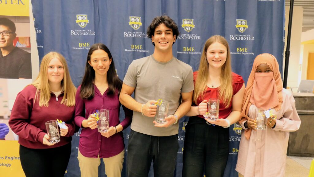
From left to right: Cassidy Christie, Audrey Yu, Vedat Duzgezen, Diana Karosas, Mariam Bamba
Supervisor

Associate Professor of Biomedical Engineering
Associate Professor of Electrical and Computer Engineering
Customer
Department of Otolaryngology, University of Rochester Medical Center
Problem Statement
The Cochlear Osia is an implant placed in the skull above the ear to restore hearing through bone conduction. There is sometimes a skull plate in the Osia implant location, and the impact of the skull plate on bone conduction is unclear. The goal of the TOBE system is thus to provide a quantitative method of evaluating the impact of a skull plate on bone conduction.
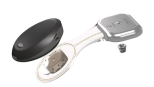
(Cochlear, 2024)
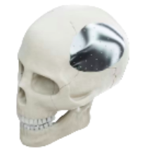
(@ksandrphoto, n.d.)
Customer Scenario
Use setting: Research
- Test how skull plates affect bone conduction using cadavers or skull models
- Other variables could also be tested
- Customers include researchers, hospitals, bone conduction implant companies
- Other stakeholders include patients who receive bone conduction implants and their loved ones
Design Concept
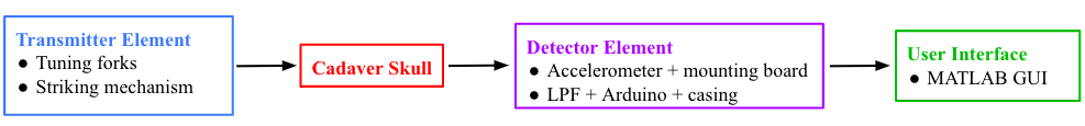
- Tuning fork frequencies: 512, 1028, 2048, 4096 Hz
- Encased with a spring-based striking mechanism for consistent vibration production
- The base of the tuning fork is placed on the skull during testing
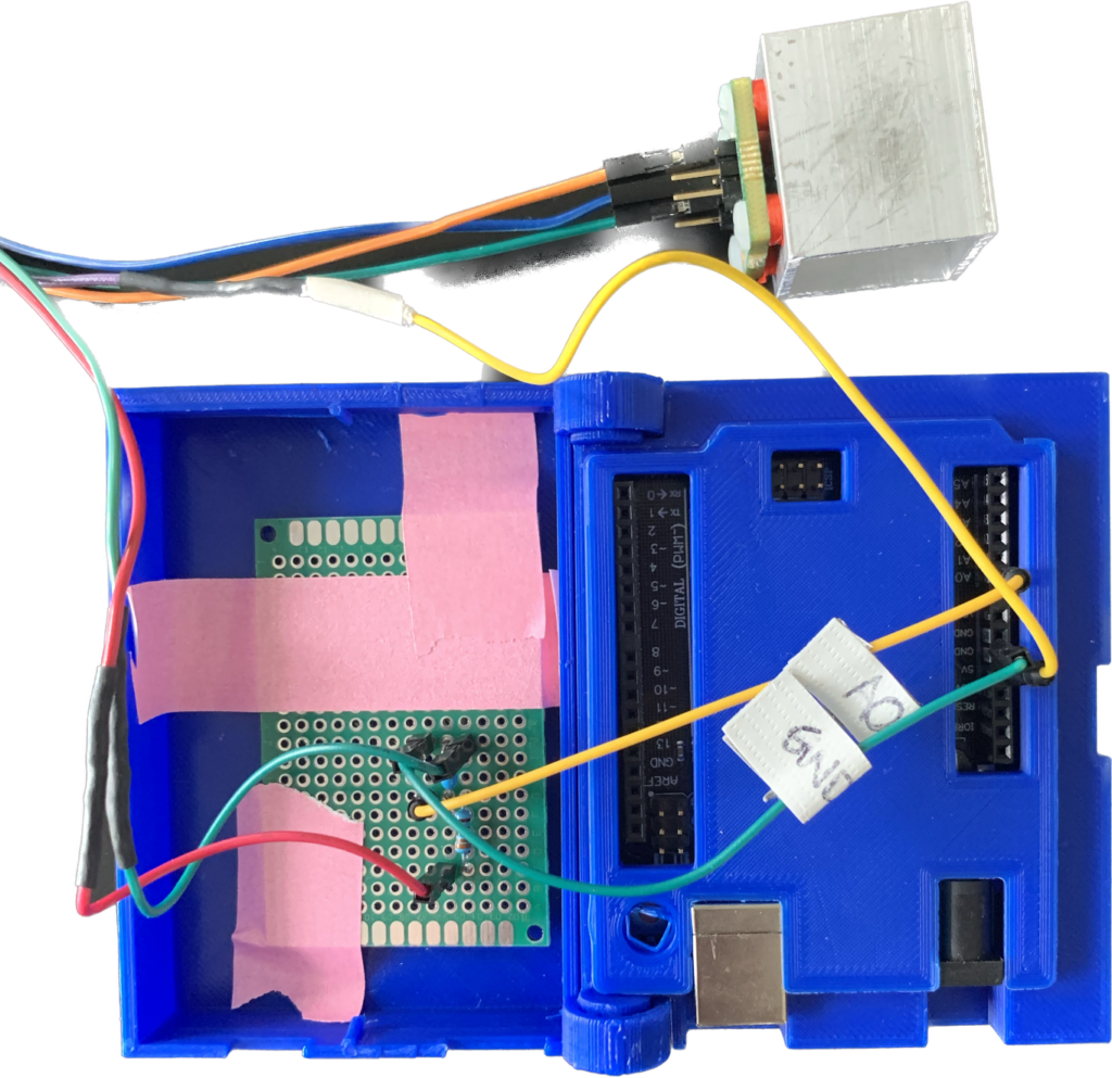
- Accelerometer detects vibrations
- Analog LPF (RC circuit) is used to prevent aliasing
- Arduino sends data to the computer for processing and display
Prototyping
Transmitter Element
Piezoelectric Buzzers
Piezoelectric Buzzers had a wide frequency range but were discarded due to issue with coupling between materials of different impedances.
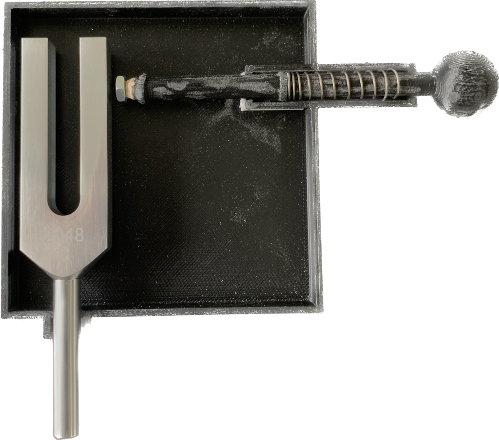
Tuning Forks
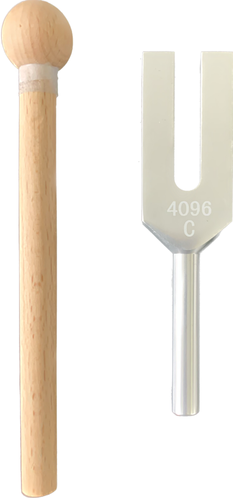
Tuning forks (chosen transmitter) can cover the the appropriate range of frequencies with a sufficient amplitude for detection. They are cost effective and practically feasible based on the mechanisms of the Rinne Test.
Tuning Fork with Striking Mechanism
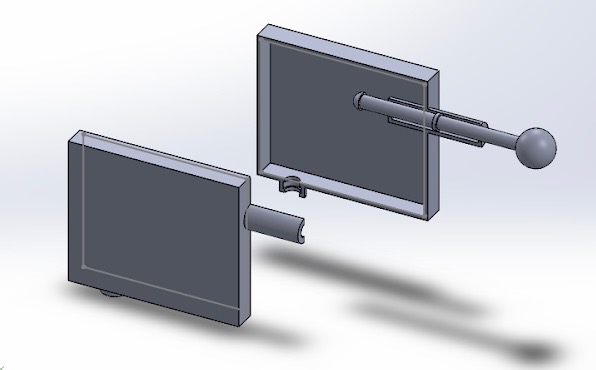
A striking mechanism used with the tuning forks to minimize variation in tuning fork vibration amplitude.
Detector Element
Headband Model
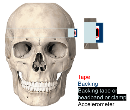
The headband model for detector mounting, where the accelerometer is held in place with a secondary support on the back of the head.
Free-Standing Model
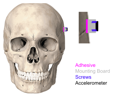
The free-standing model for detector mounting, using an adhesive between a mounting board and the skull.
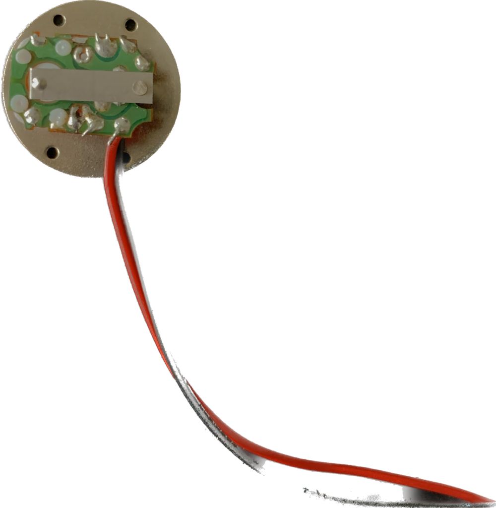
Accelerometer Mounting Board
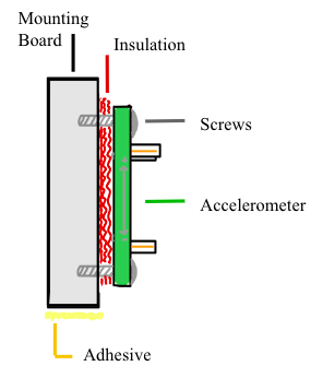
The chosen design for mounting the accelerometer. The adhesive indicates where the assembly would be attach to the bone.
User Interface
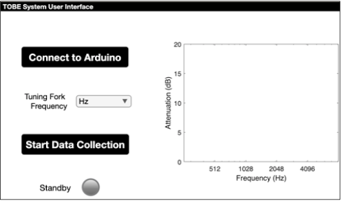
Basic functionality
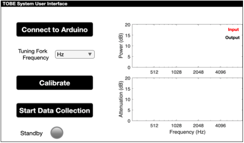
Calibration, additional plots
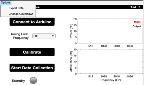
Trial #, export button, variable countdown.
Four iterations of the GUI were completed. Feedback was received after each iteration.
In the final GUI, the user:
- Inputs the tuning fork frequency
- Completes calibration to determine input amplitude
- Collects output amplitude and attenuation for n trials
- Exports data to an .xlsx or .csv file
Testing & Results
Frequency Range of Detector
The limiting factor for the frequency range of the detector is the sampling frequency of the Arduino
- fs depends on Arduino internal clock, so we tested consistency & accuracy at all input frequencies
- Input offset sinusoids using a function generator
- Plotted measured magnitude spectra
- Calculated deviation from expected spectra
- Deviation was not significantly greater than 20 Hz (p > 0.05; Wilcoxon Signed-Rank test)
→ frequency measurements are adequately accurate
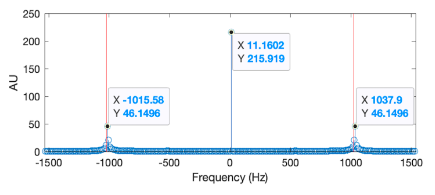
Example plot of testing results from 1024 Hz tuning fork
Transmitter Consistency
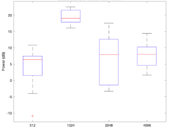
- Recorded power for 10 strikes of each tuning fork using the detector element
- Applied a chi-squared test of variance to assess whether power varied significantly more than 1 dB
- Unfortunately, the results were underwhelming, with all p <<0.01, indicating inadequate consistency across strikes
Future Directions
Recent testing has revealed that the performance of the striking mechanism falls below expectations. Moving forward, enhancing the consistency of the striking power should be prioritized.
- Modify or redesign the spring mechanism
- Introduce a second accelerometer for active calibration, removing the need for consistent striking
- Incorporate an optical interrupter to initiate data collection upon the striking of the tuning fork
- Currently, a countdown managed by the GUI instructs the strike
Acknowledgements
Thank you to Dr. Benjamin Crane for defining the problem, providing feedback at various stages of the design process, and lending us a Cochlear Osia for use during prototyping. Thank you to Dr. Regine Choe for her excellent feedback and guidance throughout the year. We would also like to thank Dr. Choe for donating an Arduino for use in prototyping. Thank you to Dr. Ross Maddox for consulting on auditory brainstem responses, audiometric measurements, and prototyping methods in early stages of the project. Thank you to Martin Gira for providing guidance on 3D printing, accelerometer selection and mounting, and optical sensors. Thank you to Dr. Scott Seidman for his frequent assistance. Finally, we would like to thank Judy Monickaraj, our project management liaison, for providing clarification and feedback throughout the year.