Team 1: Mapping & Path Planning


Team 2: Collision avoidance & wayfinding
GitHUB
Abstract
Are you tired of wasting time and money delivering packages and items around the University of Rochester campus? Look no further than our cutting-edge Autonomous Delivery Robot! This innovative solution is equipped with advanced technology, including a LiDAR camera, ultrasound sensors, and state-of-the-art programming using ROSPY (Robot Operating System for Python). The robot seamlessly combines information from various nodes, such as the perception node for obstacle detection, the path planning node for mapping, and the localization node for navigation. ROSPY also ensures smooth communication among these nodes and the HERO Development board is connected to the robot to receive motor speed commands.
The software programs are processed primarily on Beaglebone Blue, which is an all-in-one Linux-based computer for robotics, and an Ubuntu virtual machine for running the perception node to detect obstacles. The main purpose of the bot is to assist ECM and academic groups that need materials transported between buildings for labs, workshops, events, etc. These items are currently delivered manually which can be physically stressful and time-consuming. With this autonomous robot, you can rest assured that your deliveries will be made safely and efficiently, without the need for constant human intervention.
Design Process & Components
Hardware
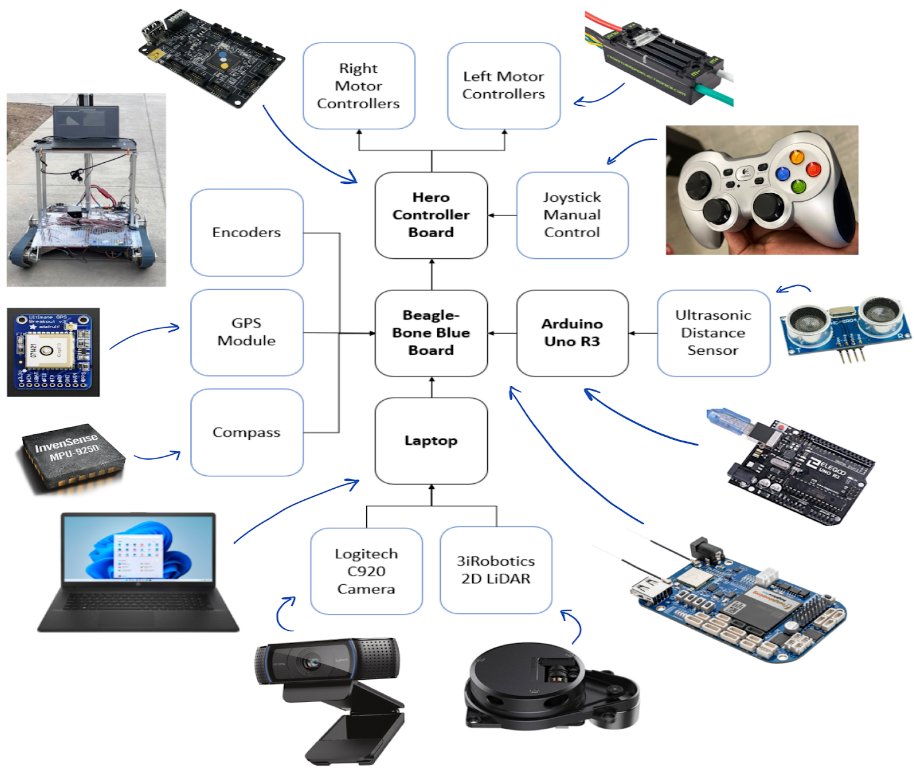
- Hardware components
- Sensors
- Compass
- 3iRobotics 2D LiDAR camera
- Ultrasonic distance sensor (HC-SR04)
- Webcam (Logitech C920)
- Optical encoders
- Adafruit GPS module
- Microcontrollers
- Beaglebone Blue
- Arduino (ELEGOO UNO R3)
- HERO Development Board
- Sensors
- Hardware Design
The following high-level diagram shows the hardware connections for the RPS:
Software
- Software components:
- Python3
- C++
- Flask framework (Python, HTML, CSS, JavaScript)
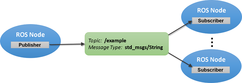
- ROS
- Software Design
ROS stands for Robot Operating System. It is a set of software libraries and tools that we use to collect all of the sensor data and prioritize it to make decisions. Every sensor input is wrapped in a ROS node. They are connected to other nodes that manipulate the data and use it to make decisions that are passed to other nodes. We decided to use ROS for Python (ROSPY) due to its versatility with different modules such as image processing. This has been a very helpful and efficient communication framework for this project. For instance, ROS seamlessly combines information from various nodes on the BeagleBone Blue and Ubuntu virtual machine to send speed commands to the HERO Development board.
The following high-level diagram shows the software architecture for the RPS.
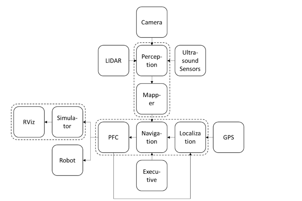
- Perception – this node takes in data from all perception sensors and processes it to make a decision. This decision to move or stop is sent out to the navigation node.
- Navigation – this node takes the map from the mapper, the current coordinates of the robot from localization, and the destination coordinates from the executive, then generates an array of smaller waypoints and sends it to PFC (Path-Following Control) – this node takes in the planned path from navigation and generates the left motor and right motor commands.
- Executive – this is the node that communicates with the user. The user inputs the coordinates of the robot’s destination through a user-friendly UI, and it sends it to the navigation node.
- Localization – this node stores the robot’s current location. It takes in data from the GPS module and PFC and then updates the current coordinates of the robot.
- Simulator – this node is a virtual simulation of the actual robot. Its job is to simulate the whole environment of the robot. It takes the left and right motor commands to update the virtual position of the robot.
- RViz – this is a ROS built-in node that allows users to visualize the simulation. It supports basic shapes such as cuboids and cylinders which can be used to represent the robot, buildings, and obstacles in the simulation.
Methods & Implementation
Each team made unique contributions to the over-arching goal of making this robot efficient, autonomous, and safe. Here they are:
Team 1: Mapping & Path Planning.
The mapping and path planning team ensured the robot accurately moved between two designated points with no human control during the movement. The only instruction given to it is where it needs to go – at the beginning of the movement – and the internal programming will get it there.
The way we make this work requires three separate processes/packages: ‘Navigation’, ‘Localization’, and ‘Path-Planning’. Navigation takes as input the robot’s destination’s GPS coordinates, and with them, uses an API to generate a list of intermediate points the robot should take to reach the destination. These are called waypoints. The waypoints are generated such that the robot can move from one to the other in a straight line motion, through paths walkable by pedestrians, and without any stairs or fixed obstacles.
The localization package is extremely crucial. This package tells us where the robot is at all times during its journey. It contains three programs interfacing with three sensors: two optical encoders, a magnetic compass module, and a GPS module.
The path-planning package is where everything comes together. Given that navigation has sent a list of straight-line waypoints, and localization tells us where the robot is, it’s the path-planning’s job to orient the robot to point towards the next waypoint and move towards it. This is therefore the package that directly controls the motors and is the icing on the cake.
Team 2: Collision Avoidance & Way-finding.
This team had two main goals. To ensure the robot detected obstacles such as pedestrians and stairs and detected a clear lane that it can follow and stay on. To achieve these two goals, three levels of detection – three sensors were used: a 2D LiDAR camera, two Ultrasonic HC – SR04 distance sensors, and a Logitech C922 webcam for image processing. Each group of sensors has its own Python program or ROSPY node that sends obstacle and lane notifications to the central perception node. This final node has an algorithm that determines if it is safe for the robot to move and informs the navigation node.
- Ultrasonic ranging sensors
The ultrasonic ranging sensors are the highest-priority obstacle detection sensors in our project. We decided to use two ultrasonic sensors placed in front of the robot (left and right) on its body about 9 inches from the ground since they have a distance range of 2 cm to 50 cm to detect short obstacles. The 5V ultrasonic sensors are connected to an Arduino UNO R3 board with a Python program that collects the ultrasonic readings and sends them out to Beaglebone Blue via a USB connection. A ROSPY node for the ultrasonic sensors reads the data from the message and sends it to the perception node for processing using a custom message. However, these sensors are limited due to their field of view being linear and uniplanar, hence the need for more levels of obstacle detection.
- 2D LiDAR camera
The second level of obstacle detection is the 2D LiDAR camera that detects obstacles in a 5m range around the robot. We decided to limit the range of detection to 1.5m and to focus on obstacles directly in front (30 degrees) of the robot to avoid stray signals. During each measurement process, the laser radar emits a modulated infrared laser signal, which is received by the optical vision acquisition system of the LiDAR after being reflected by the target object. The data is then processed by the MCU processor inside the Delta-2A laser radar for real-time data processing. Ultimately, the distance from the target object to the sensor and the current angle is calculated and outputted to the external device through a ROS Laserscan message. The perception_lidar node finally sends a message to the master perception node when an obstacle is detected in the area in front of the robot.
- Image Processing with Webcam
The webcam image processing helps primarily with lane detection and with obstacle detection as the third and final level for obstacles that may be missed by the aforementioned sensors. The webcam node takes frames from a live video feed and does image processing on each frame to detect lanes, obstacles, and stairs. To achieve this, we imported OpenCV (cv2) which provides a real-time optimized Computer Vision library, tools, and hardware. Our image processing algorithm leverages some CV2 functions and concepts such as edge detection (canny), HSV, and morphological transformations for image segmentation and noise removal. Our lane detection algorithm relies on HSV (Hue Saturation Value) which allows color distinction to pick the path that the robot should take. We can blur all 120-180 HSV values that are green and set those to black and white instead. There are challenges brought by shadows in some images that limit the effectiveness of the algorithm but can be easily solved with LiDAR data to ensure the path is clear. Our webcam obstacle detection algorithm applies a mask on a frame to limit the area of interest up to 1m or less for small objects missed by ultrasonic distance sensors and the LiDAR camera. Then, it finds all contours that may be objects and draws a bounding box around it. The results are sent to the perception node for final processing.
- Interface
We have developed an interface that enables users to choose a location for our robot to navigate to. Once the user selects a destination and clicks the “Go” button, the application sends commands to the terminal to log in to the BeagleBone server and launch the navigation file using ROS. The program also sends the location that the robot is supposed to go to. We built the interface using Flask, a web framework for Python. In addition, the interface includes visual elements that allow users to easily recognize the selected destination and interact with the robot without having to use the terminal. Below is what it will look like.
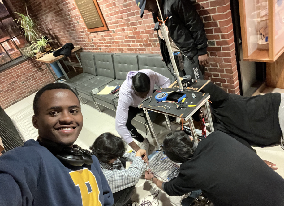
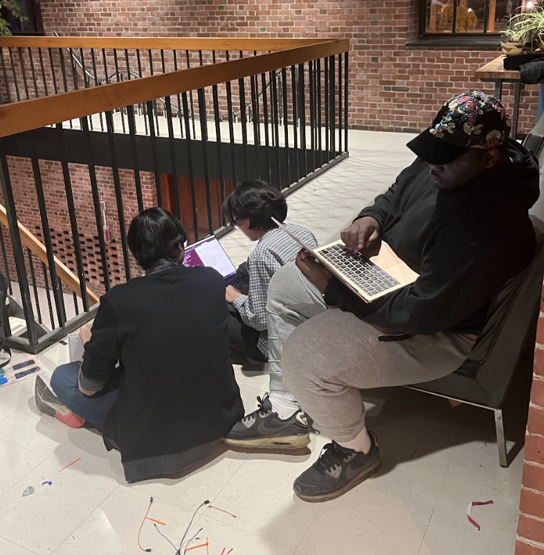
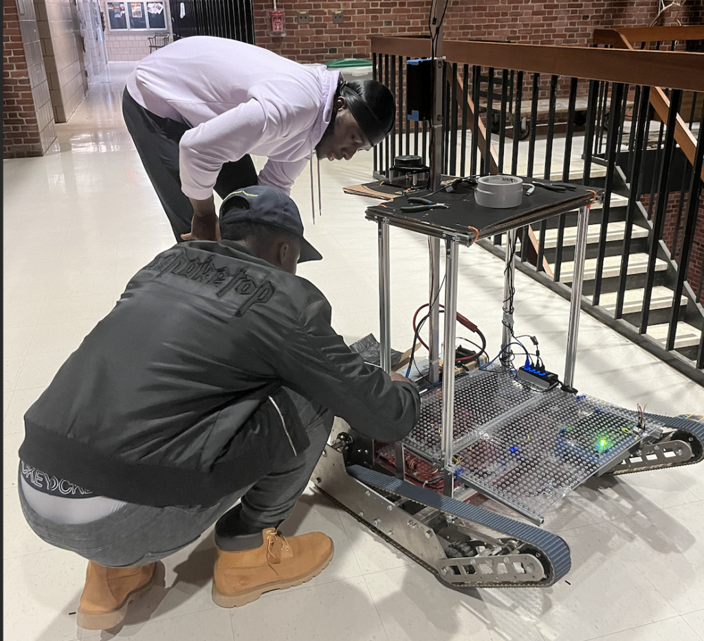
Captured on camera: Results & The Process
Here, you will see some pictures and videos documenting the process and the results!
Here’s a cinematic walkthrough of how our algorithm works and takes input from the camera to determine where and where not to go. Basically, this is the robot’s point of view.
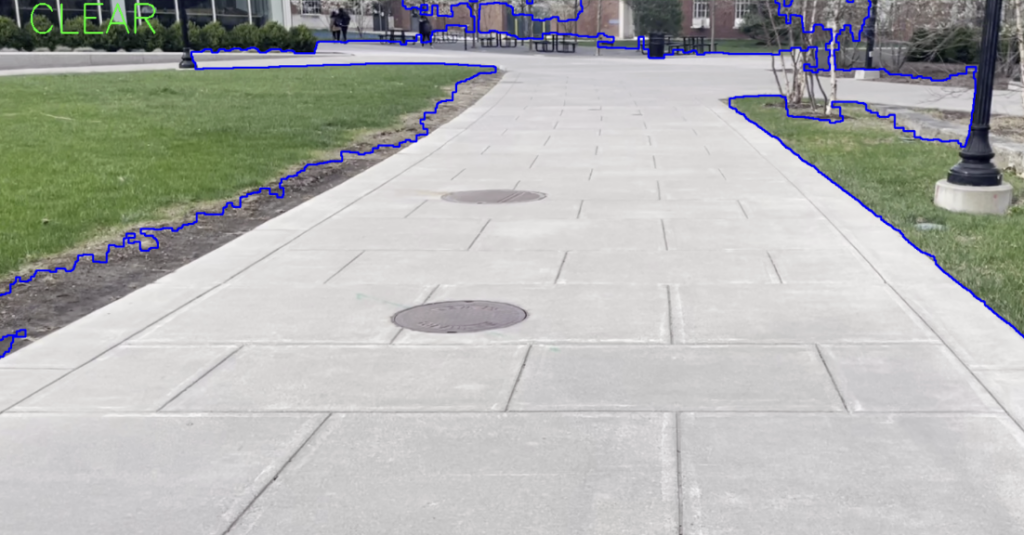
First, the video footage. What the camera and the human eye sees:
Then, we have HSV segmentation applied and results in identification of a lane as shown below:
Additionally, we have the Gaussian blurring and Canny-Edge Detection section of our algorithm that also applies a triangular mask to identify obstacles in the lane.
Finally, after drawing colored lines and bounding boxes around obstacles, we have the final result. The camera will indicate the passable lane in blue, and the robot can navigate in the clear lane.
In case of an obstacle, the display shows that an obstacle was detected and a stop is activated after confirming with other sensors.
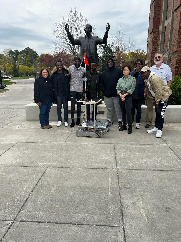
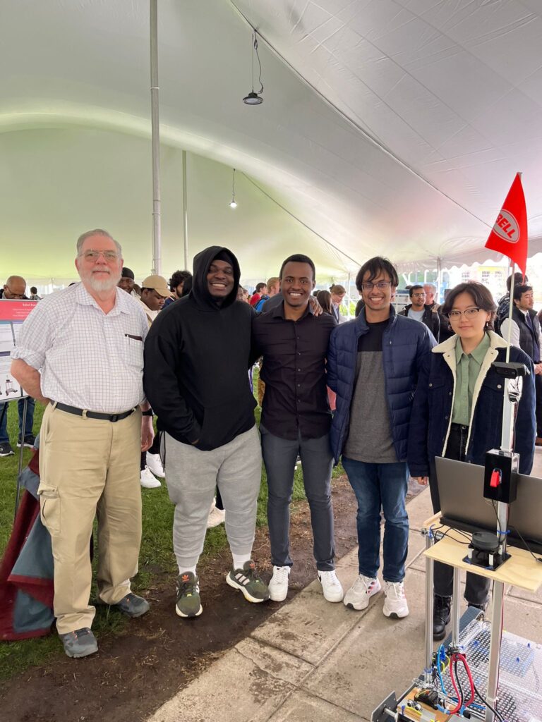
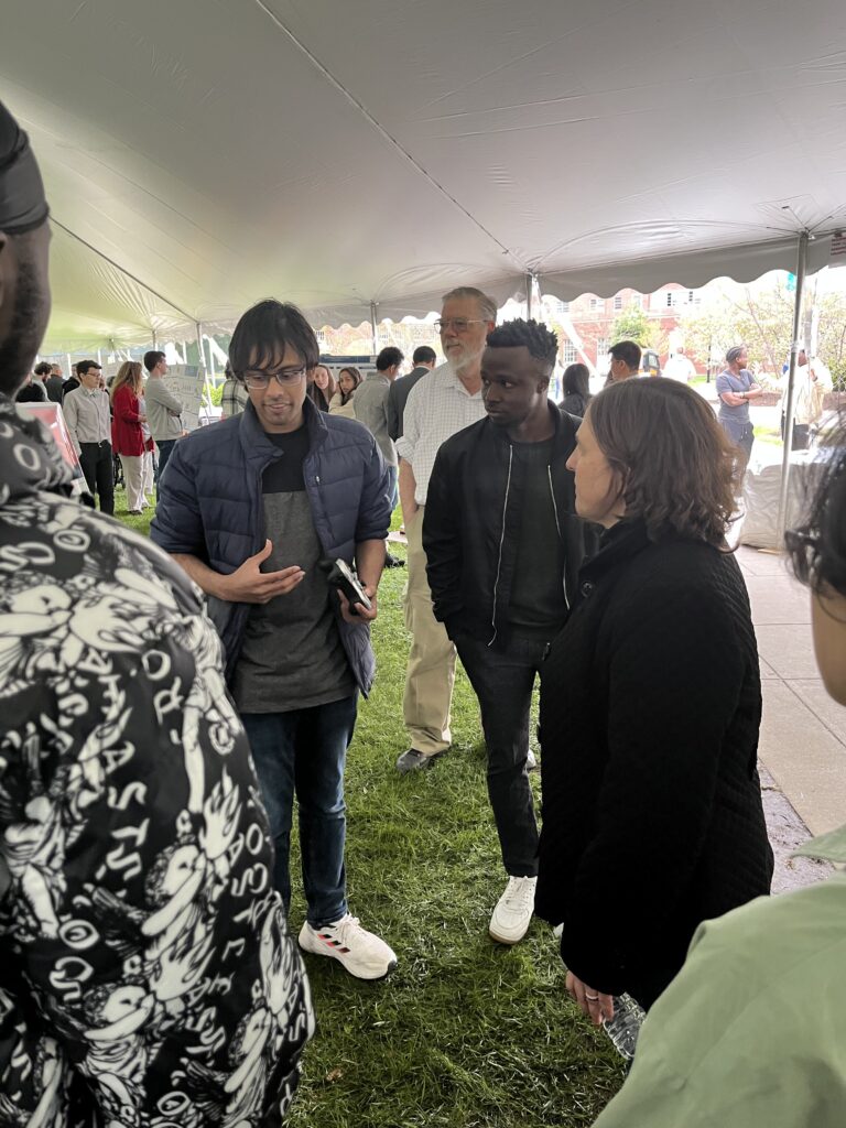
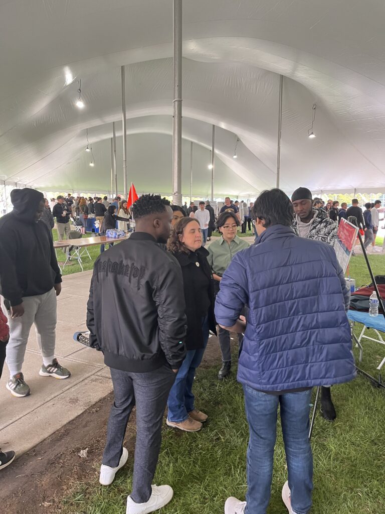
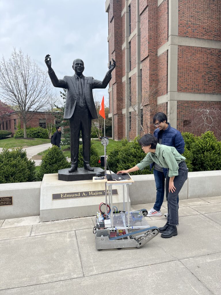
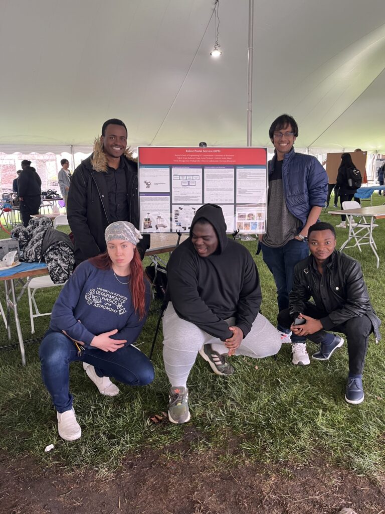
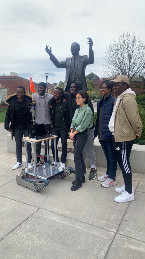
Senior Design Day
Challenges & Future Recommendations
- The HC-SR04 Ultrasonic sensors seem to be doing their work perfectly fine with their 50cm range but less sensitive and more accurate ultrasonic sensors like the MB7040 I2CXL-MaxSonar-WR would offer better range and IP68 weather-resistant modifications.
- The GPS was limited by accuracy. To enhance the GPS accuracy, one can buy two Sparkfun’s GPS-RTK Ublox ZED-F9P modules instead and use Differential GPS (DGPS) to achieve mm-point accuracy. Another approach is to have a detailed local map of the area of interest (entire campus) programmed inside or scanned using a 3D LiDAR for better accuracy and efficiency for the specific project scope.
- The current image detection algorithm (HSV-centric) does not account for any intense shadows that may be cast on the ground, because the contrast between the pavement and the shadow is too high. In the future, it would be ideal to perform shadow detection to deal with this edge case.
Copyright © 2023 RPS. All rights reserved.