The solar steam turbine is a design that uses a femtosecond laser-processed superwicking metal sheet to generate electricity via steam generation.
The People

Miles Titzer: Project Coordinator, Solar Collector Lead
mtitzer@u.rochester.edu

Frederick Crumbo: Scribe, Capsule Lead
fcrumbo@u.rochester.edu
Customer: Subhash Singh
Advisors: Chunlie Guo (PI), Greg Schmidt
The Purpose
Dr. Chunlei Guo’s research on laser-manipulated metals has led to properties such as high optical absorptivity and strong hydrophilicity. This work has inspired our customer Subhash Singh, a colleague of Dr. Guo, with the idea of a turbine that takes advantage of these materials to self-sustainably power an electric device.
The product is a solar-powered steam turbine that uses focused sunlight to generate steam, powering a turbine and creating electricity. It features a closed capsule containing an optically-treated metal target on which water will be turned to steam, thus creating pressure to power the turbine. Ideally, it will provide a more efficient method of using sunlight to create electricity.
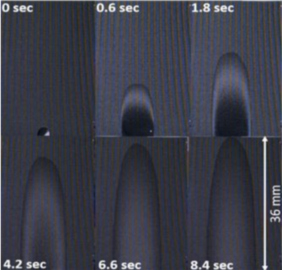
This image above shows how the optically processed superwicking metal draws water upwards via capillary effect. When highly illuminated, target absorbs light creating heat that can create steam by evaporating the water on the surface. This image was provided to our team directly by our customer.
The Project
The evolution of the capsule:
Based on our capsule’s rough sketches and specifications, the first model of our steam capsule was designed in SolidWorks. We began with a simple rectangular extrusion with a wall missing in which we will place a transparent material to complete the seal. Next, we extrude cut entry and exit ports and dimensioned the capsule in accordance with our specifications. From there, most of the alterations were in order to shape down our model to guide how the water settles and to enable an easier 3D print.
There were two main problems with this design. The first is that the volume of this model was rather large. This would cause problems with pressure build-up. The second problem is that there would be a
risk that the steam would have no physical preference for the steam port over the water port. This would disrupt the cyclical nature of our model in which all of the power of the steam is transferred to the turbine.
The design depicted in Figure 2 solves both issues. To solve the first issue, the shape of the capsule was changed so that it would more tightly follow the target. Additionally, in consideration of the higher pressures that would be present As for the second, we have been looking into valves that will be able to control the direction of flow to place in each port.
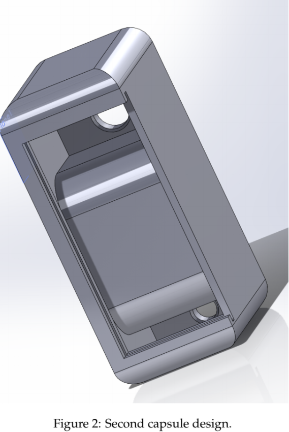
To make the design even more compact, the empty space leading up to each port was gotten rid of. To enhance the prospects of a strong print, the walls were thickened and the rounded edges were eliminated. Thicker walls also helps mitigate pressure risks. By using a lid mechanism on the front, waterproofing of the inside is made possible. Before the transmissive wall is inserted, the inside can be coated with a waterproofing substance.
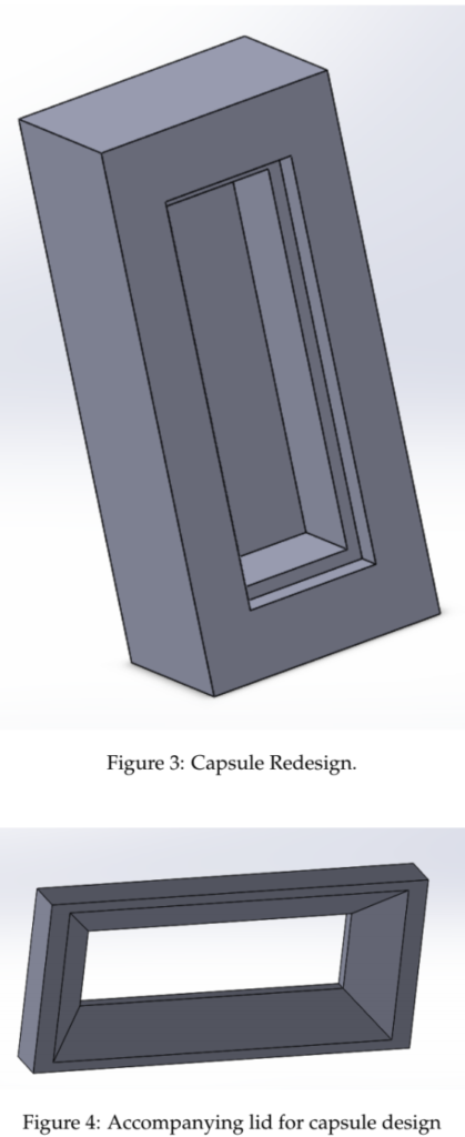
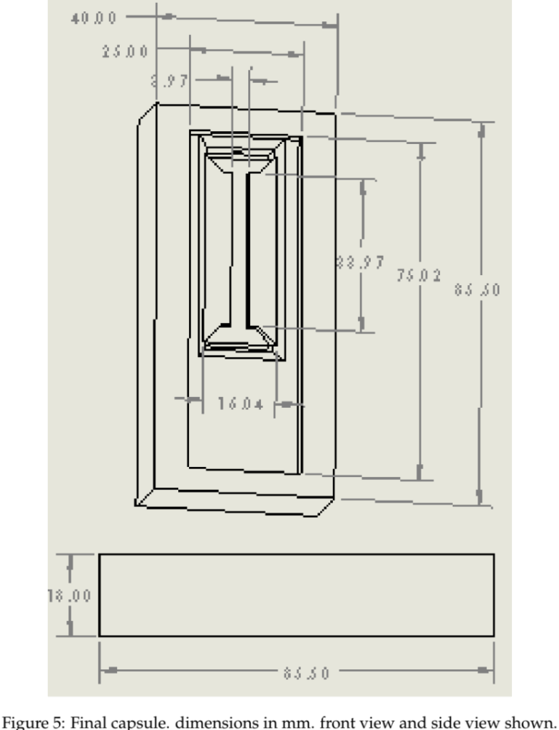
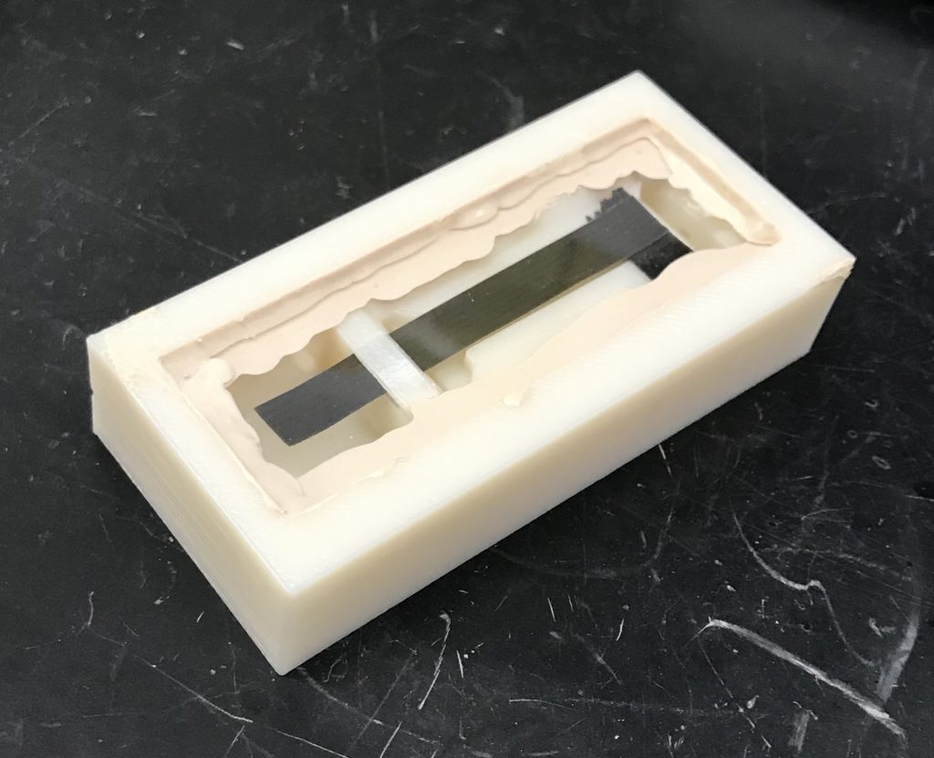
The final iteration of our capsule is reoptimized in multiple ways. Primarily, we continued to decrease the volume of the capsule. As this was done, the sample compartment became shallower. This was needed to make sure that no light was blocked by the capsule walls, and so that all of the solar energy can reach our sample. Due to the decreased volume between the window and sample, a channel behind the sample was created for water (gas/liquid) to flow. Along with the shallower sample area comes two divots at the head and foot of our sample. These ensure that our valves can be properly assembled without interfering with the sample surface.
Finally, this prototype in particular has small pilot hole to control steam pressure during our first trials. The structure of this capsule can accommodate a standard microscope slide as well as plexiglass cutouts. We needed a capsule capable of accepting both window designs as our temperatures and pressures change. Both windows will be sealed with high temperature liquid rubber silicon.
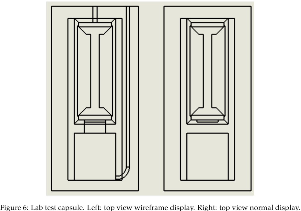
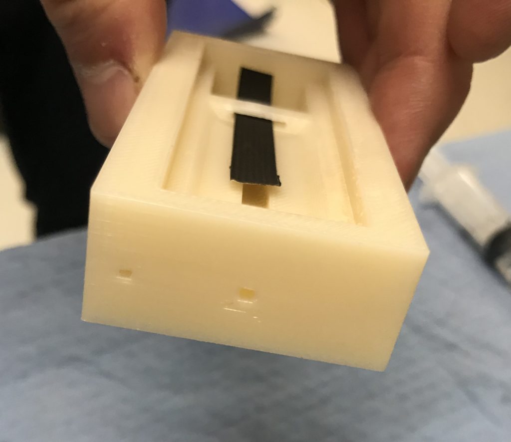
For the sake of testing in the lab environment with a controlled supply of water, an additional capsule has been 3D printed (Figure 6). This model features a water reservoir and a capillary for ease of input
of water without the condensation tube and such. For a given test, water will be drawn via capillary action with a sample that is long enough to extend down into the reservoir through the slit that joins the evaporation compartment with the water reservoir.
The evolution of our solar collection:
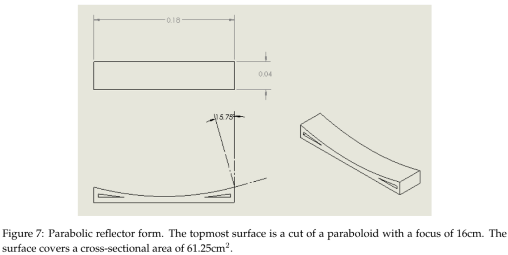
Based on our specifications, we designed our first model of our parabolic reflector form in SolidWorks (Figure 7). We began with a paraboloid shell and cut it such each cross-sectional dimension is √ 30 times that of our target, thus ensuring that the irradiance of the sun will be magnified between 20 and 30 times as requested. For the sake of a low angle of reflectance and a reasonably distanced focus, the normal of the paraboloid was set to max out at 15◦. Support structure was added in order to reduce risk of mechanical aberrations of the surface form. After meeting with Greg Schmidt, we came to the conclusion that the design would be better as a parabolic cylinder than a paraboloid (see Figure 7). We had originally eliminated this possibility under the impression that such a design would lead to inconvenient dimensions: a very slim width and a very long length. However, by orienting the capsule such that the long dimension of the target is perpendicular to the long dimension of the reflector, the dimensions of a parabolic cylinder form come out to be very
similar to those of the paraboloid design (only differing by a few millimeters in each direction).
This design consists of an extrusion with a parabolic top surface. The width of the surface is 3.5 cm to match the length of the target, and the length is 17.5 cm, 25 times the width of the target. The focus
was fixed at 16 cm above the surface apex leaving a maximum 15.75◦ normal. Support structure was again added in order to reduce risk of mechanical aberrations of the surface form.
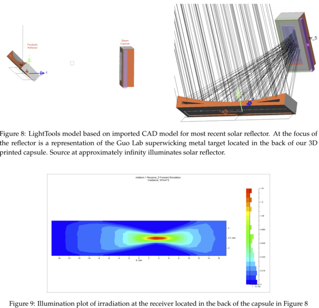
A LightTools model of the system as a whole was produced to determine the proper positioning of each element such that the sun’s rays will optimally fill the target. This will guide our design for a support structure that will fix the capsule at a sufficient distance and orientation relative to the collector. Coordinates and orientations were optimized simply for maximum incident power: our customer has decided that power distribution is not of concern.
Our model consists of a sufficiently small and distant source that its aim area fills our imported reflector with collimated light. For the purposes of this model, attributes of the sun’s spectrum and geometry need not be taken into account: we are simply interested in how the sun’s rays arrive at our receiver. The reflector was configured with coarse geometric tolerances (representing a somewhat rough print) and a 92% reflectivity (a conservative underestimate). To represent a plexiglass window, a thick sheet of 92% transmissive material was placed in the front of our imported capsule CAD element. A receiver was positioned in the back of the capsule, which was at the focus of the reflector.
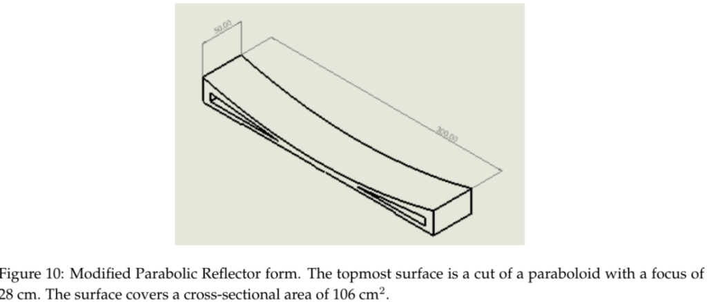
With this optimized configuration, by comparing the power incident on the reflector with that which struck the receiver, we see that 72% of our light was actually making it to the superwicking metal target (versus 81% used for Photon Budget calculations). In response to this, a slight modification was made to the reflector making it now long enough to focus 30 kW/m2 onto our target despite these losses. This is the highest solar concentration we were instructed to design for. We can lower the delivered power as necessary by simply covering portions of the reflector with absorptive materials.
The Possibilities
Having just obtained the superwicking metal sample that lies in the center of our project, our most recent development is a complete evaporation capsule that will be ready for tests as our project transitions into the lab testing phase.
In order to perform, it is necessary that the capsule includes a means of water insertion. For tests, water will be injected via syringe into the water entry-port that connects to the reservoir at the bottom end (opposite end) of our capsule.
By feeding water into the entry-port, tests can be performed with a particular amount of water in the initial state that can be compared with the water leftover. This provides a means of measuring the volume flow rate of the steam. By determining the loss of water weight over the time of focused illumination, volume flow rate can be analyzed directly.
Of course for such a test to be accurate, it is necessary that the capsule is waterproof. This was demonstrated by filling the reservoir to the brim and observing how far the water level sank after 10 minutes.

It is clear that after 10 minutes, no water escaped the reservoir, evidencing its validity as a water-sealed capsule.
This work will be continued by Dr. Guo’s lab over the summer. Our project in a state of transition in which we are informing a student who is posed to assume control of this project as to its status quo.
If our deliverables prove effective, they will be introduced in a closed system featuring a steam turbine that will give merit to the steam produced.
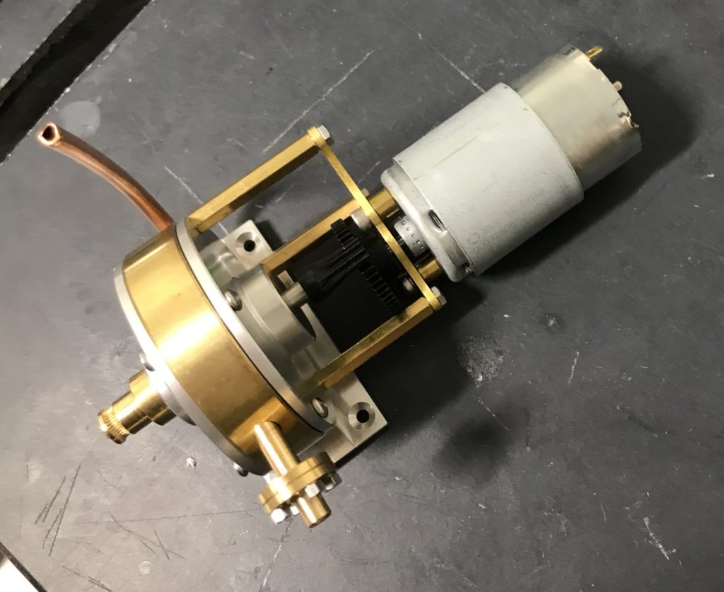
The closed system will feature our capsule, this (or similar) steam turbine, and a condensation tube, complete with valves for controlling the flow of water/steam throughout the system. Our team has already located potentially viable parts for each of these components.
Team Thermo wishes to thank the following for their time, effort, and assistance: Subhash Singh, Chunlie Guo, Greg Schmidt, Wayne Knox, Duncan Moore, Meir Brea, Ed Herger, and James Alkins.