PROJECT DESCRIPTION
THE TEAM: Alex Labonte, Duncan Dang, Je Jun Youn, Yujin Nakamoto; Prof. Mottley and Prof. Phinney as our advisors
The task: To retrofit a scale model of a forklift (or similar warehousing vehicle) with an autonomous system capable of the following: i) navigating a bounded arena; ii) detecting and classifying objects of a regular cubic geometry but of different colors (labels); and iii) relocating these objects to their respective zones. In summary, we attempt to design a physical classifier.
THE SPECIFICATIONS: We put forth ideal characteristics for both our robot and for our demo-objects.
- [ROBOT] The robot should be capable of lifting objects up to 5 lbs. in weight.
- [ROBOT] The robot should be capable of detecting packages and release zones within the arena, as well as of discriminating them based on their labels.
- [ROBOT] The robot must autonomously navigate from starting zone to target package. Upon arrival, the robot should acquire the package (by lifting it). The robot must then autonomously navigate from package zone to release zone, the appropriate station having been identified by classifying the label of the current package. Finally, the robot must deposit the package (by lowering it).
- [OBJECT] Target packages should be regularly-dimensioned with a cubic geometry. They must sit on a base that can ‘mate’ with the lifting mechanism of the robot.
- [OBJECT] Target packages should be labeled by color so as to be identifiable and classifiable within the arena.
- [OBJECT] Target zones should be similarly labeled to receive packages of a matching color.
PROJECT DESIGN
THE COMPONENTS: After dissecting our baseline forklift (a Top Race TR216) we compiled a final list of parts for our retrofit.
- Raspberry Pi 4 Model (Broadcom BCM2711 @ 1.5 GHz, 4 GB SDRAM)
- Raspberry Pi Power Regulator x 2
- Raspberry Pi 4 Micro-SD card
- Raspberry Pi 4 Case
- Lift Motor (12 V DC worm gear motor)
- Lift Motor Electronic Speed Controller (30A brushed ESC)
- Drive Motor (12 V Brushed Motor)
- Drive Motor Electronic Speed Controller (60A brushed ESC)
- Steering Servo (full metal gear digital servo)
- Z-Axis Slide Table
- Ultrasonic Sensor x 4 (HC-SR04)
- USB Webcam (640 x 480 px.)
- LiPo Battery (7200 mAh @ 11.1 V)
- LiPo Battery Charger
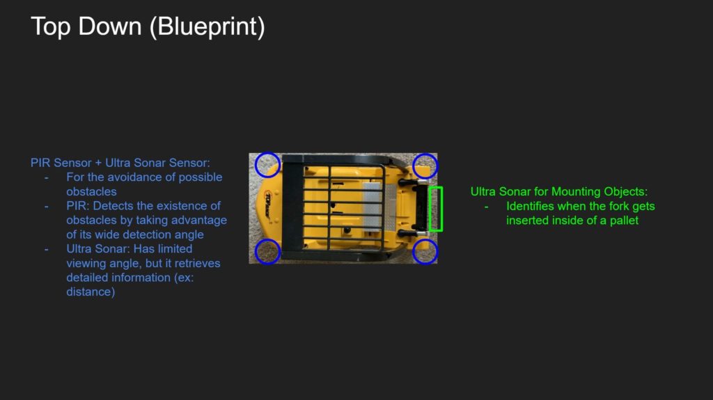
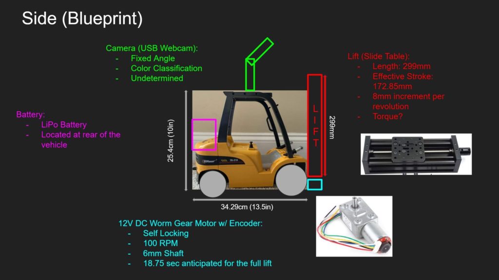
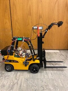
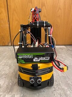
The Initial Design: The hardware team removed all electro-mechanical components from the original forklift, after which we proposed the installation of the following: i) a forward-facing webcam mount; ii) a rugged slide-table-based lift with lift-motor; iii) a new transmission; iv) a rear battery; v) onboard guidance computer (the Raspberry Pi); and vi) an ultrasonic array. Click each gallery to view photos in lightbox mode.
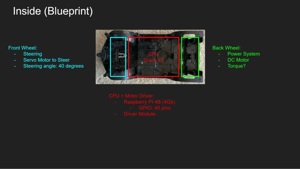
In continuation from last semester’s reverse engineering project, we decided to preserve the toy forklift’s chassis. The implementation below began by removing the plastic hull from the RC forklift. To the remaining structure, we proceeded to install our purchased components and 3D-printed parts.
PROJECT IMPLEMENTATION
THE TRANSMISSION: The picture on the left presents our initial attempt to build a transmission. The prototype was constructed by press-fitting a worm gear to our DC motor shaft and pinning a center gear to the driving axle. Both gears were 3D-printed with black PLA material with a mechanical conversion ratio of 40:1. The underlying principle was that the two gears would complete the drive train from the main motor to the front wheels. Unfortunately, due to the limitations of our 3D-prints, our prototype encountered significant issues:
- Multi-layered 3D-printed gears increased static friction, which led to an irregular (and rough) transmission
- When a high-duty-cycle PWM was fed to the drive ESC to overcome said friction, the kinetic friction caused the spinning gears to melt.
- While the gears were always intended to be disposable components, this failure mode always led to labor and time-intensive maintenance.
The picture on the right presents our final transmission. To troubleshoot the issues above, we promptly decided to replace the entire transmission system. Instead of a worm gear we installed a differential gearbox, which was connected to the drive motor by a 3D-printed coupler. As a result of these changes, the transmission became much smoother. Nevertheless, there were some few takeaways:
- The gearing was predetermined in the gearbox as a 1:1 ratio. This caused our transmission to run too fast.
- The limitations of the 3D-printed material did not change. The coupler, while requiring less frequent maintenance, remained a disposable component.
Fig.: The initial 3D-printed transmission with worm drive. Excessive friction often led to mechanical breakdown with melting of the gears as the dominant failure mode. 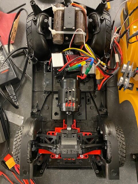
Fig.: The final transmission, salvaged from an RC car. The gearbox is differential. The motor drives the input shaft via a 3D-printed coupler.

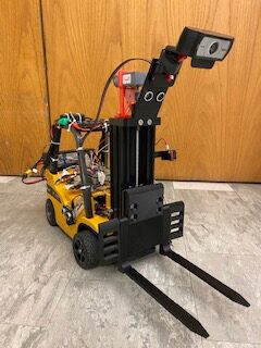
THE LIFT: Arguably one of the most essential functions of a fork-lift is its ability to lift packages and as such we wanted to design this component in a robust manner. We needed a lifting mechanism that would be able to lift in a slow and controlled manner, had enough torque to pick up any package up to and including a weight of 5 lbs., and have a robust lifting mechanism that would be strong enough to handle the stresses of a heavy package.
Rather than leave some elements to chance and take the lift design in our own hands, we decided to use a sturdy, 50cm Z-axis slide (pictured below) to lift in a smooth and controlled manner as well as be sturdy enough to handle the forces of heavy packages. We then used the pitch of the lead screw on the Z-axis and the average lifting rate of real-world forklifts to find a motor that would supply sufficient torque to lift our average 5 lb. package in a slow, controlled manner. We also decided that we should use a motor with an encoder so that we could keep track of the position of the lift as it changed its elevation.
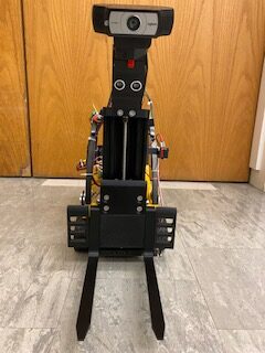
To make a forklift out of this Z axis slide, we designed and 3D-printed a modular system of forks and also a means to mount them to the slide. The forks were roughly based on the design of the forks on the original Top Race forklift. To complete the lifting mechanism, we designed and 3D-printed a mount for our camera into which we integrated a front ultrasonic module to be used to measure the distance to the package. Lastly, we made stabilizing brackets to mount the Z-axis to the Top Race forklift’s body and chassis, as well as to hold our lift motor in place.
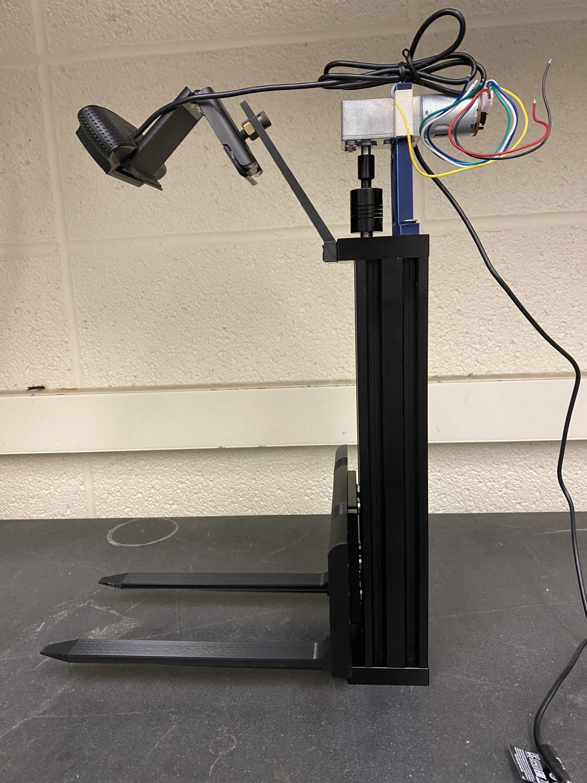
Fig.: The Z-Axis (plus peripherals). 
Fig.: Lifting >5 lbs. 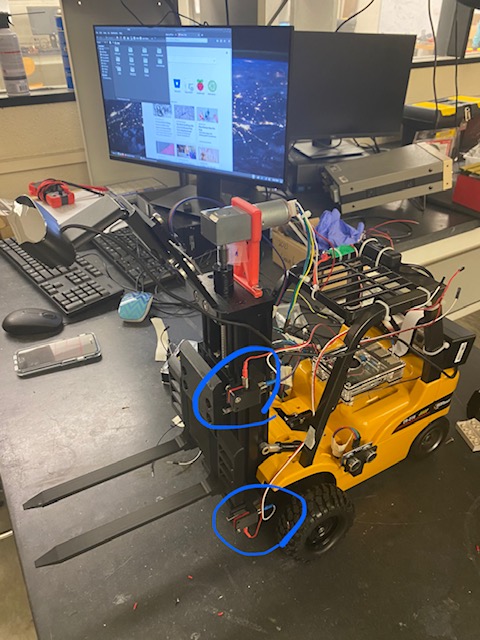
Fig.: Limit switches installed.
THE STEERING: From the outset of designing the steering system, we knew that we wanted to rely on a servo. This is because servos are capable of rotating by an arbitrary relative angle. This was essential: the vehicle needs to momentarily adjust its steering according to relative position of the target package and release-point.
Fortunately, the base chassis came with a simple yet effective steering structure, a slotted steering bar. We therefore decided to take advantage of it and printed a cylindrical plug (attached to the servo horn) to mate with the bar.
Once the steering system was installed, we tested it with a receiver and a transmitter to ensure that the wiring did not have an issue. We then proceeded to driving it via software.
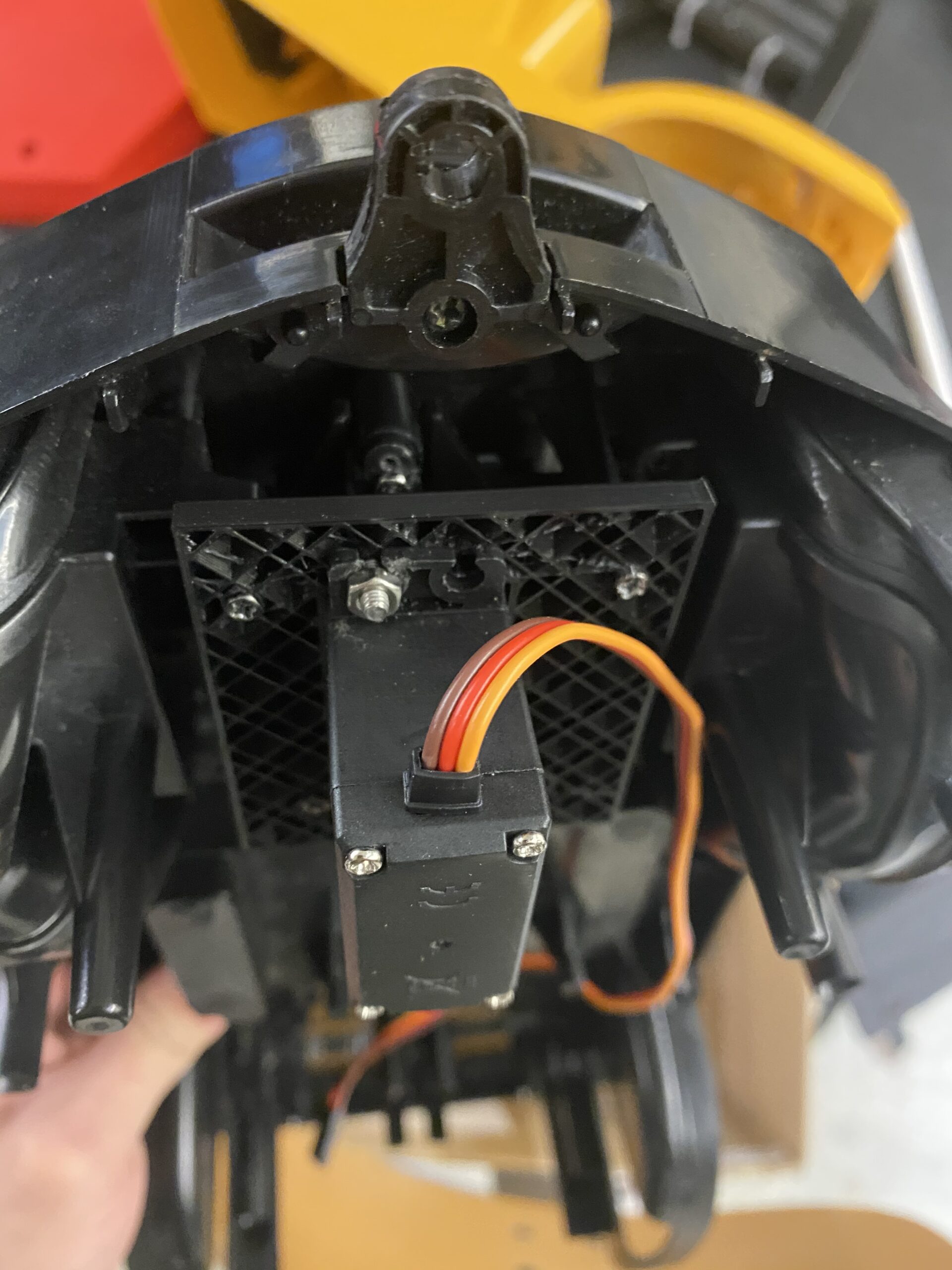
Fig.: Rear steering is accomplished with a ‘rudder’, a digital servo slotted into the control rod. 
Fig.: Testing the servo with an RC transmitter.
The Drivers: The forklift is autonomously operated by an onboard Raspberry Pi 4, which interfaces with the following peripherals via its 40-pin GPIO header: i) the lift motor ESC; ii) the drive motor ESC; iii) the ultrasonic array; iv) the slide table limit switches; and v) the steering servo. In addition, the Pi boasts four USB ports, one of which is connected to the onboard front-facing camera.
The lift, drive, and steering each require their own pulse-width-modulated (PWM) control signals. Though not ideal, our Pi generates these signals in software: the RPi.GPIO library is capable of issuing PWM from any GPIO pin via the Broadcom chip’s DMA controller. With the exception of the lift motor, which receives a 62.5 Hz signal, all ESCs and servos take a generic 50 Hz PWM.
It should be noted that while these are low frequencies, the software PWM is imprecise; artifacts in timing are why our forklift appears ‘jittery’ overall. To make matters worse, we do not make use of (real) interrupt handling (in general, it is difficult to implement true ISRs on the Pi). For this reason, we opted not to decode the quadrature signals from our lift motor’s encoder. Instead, the (absolute) elevation of the forks is detected by limit switches.
Each ultrasonic sensor is interfaced with via a TRIGGER and an ECHO signal. As may be expected, the former emits the ultrasound while the echo issues a logic-HIGH on its return. Each sensor in our array requires a voltage divider to reduce the 5 V ECHO to a 3.3 V signal for the Pi.
Fig.: Testing our ultrasonic sensor (with voltage divider). 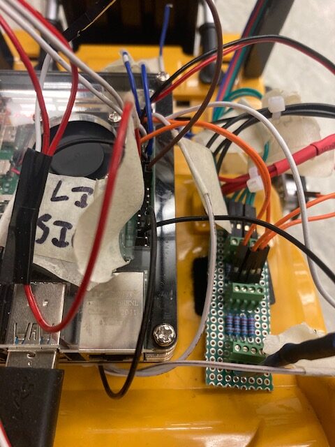
Fig.: The 40-pin header alongside final voltage divider circuits (for the ultrasonic array).
THE ENVIRONMENT: We field-tested multiple Linux distros in the course of fine-tuning our demonstration. Some (e.g., Ubuntu MATE) had more modest hardware requirements than others (Ubuntu). This was important: the more lightweight the OS, the better the performance of our core guidance, vision, and device-driving code. Ultimately, our robot runs on Raspbian.
Remote access to the onboard Pi is provided via RealVNC. Upon booting, the Pi launches a VNC server into which we can cloud-connect from any desktop environment with VNC Viewer installed.
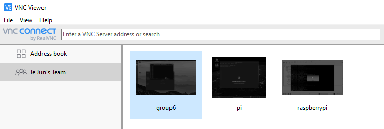
Fig.: Cloud-connection to our Pi via VNC.
THE CAMERA: All image-processing is performed via OpenCV. The guidance controller performs closed-loop steering by reading the front-facing webcam at 50 Hz (at a resolution of 640×480). In box-approaching mode, each frame is processed as follows (without loss of generality, here we focus on red boxes):
- Map the raw BGR image to the HSV color space (which is better for object discrimination).
- Mask out the ‘red’ regions of the image (defined by hand-tuned upper and lower bounds).
- Having detected every red contour of the image, draw a bounding rectangle over each.
- Filter out the ‘biggest’ rectangle (greatest area). Assuming this to be the box, return the centroid of the bounding box.
At every iteration of the control loop, the motor controller receives the coordinates of the centroid. The response is generated as a stimulus to the steering servo, which is itself computed by taking the horizontal deviation between the target centroid and the central vertical axis of the image frame (at an x value of 320 px.). In effect, this is proportional control.
The process is similar for approaching the blue release stations. The main difference is in discriminating between release stations of different labels: after drawing a bounding box over each ‘blue’ target, we perform an additional color-detection pass over the top left quadrant of each blue contour. Since each release station bears its label as a colored piece of cardboard (on its top left), we can use this method not only to filter out blue regions that aren’t release stations but also to identify which colored box the station is supposed to receive.
Last, note that the camera feed is also used to terminate the guidance controller. By deriving the ‘width’ of the target (whether it is a package or a station) and comparing it to a threshold value, we can approximate the current distance between the target and robot.
Fig.: An un-calibrated color-detection script (taken from StackOverflow). 
Fig.: Tracking the ‘red’ box. Note that the white dot is where the robot has located the target. 
Fig.: We began by implementing ‘bang-bang’ control before proportional control.
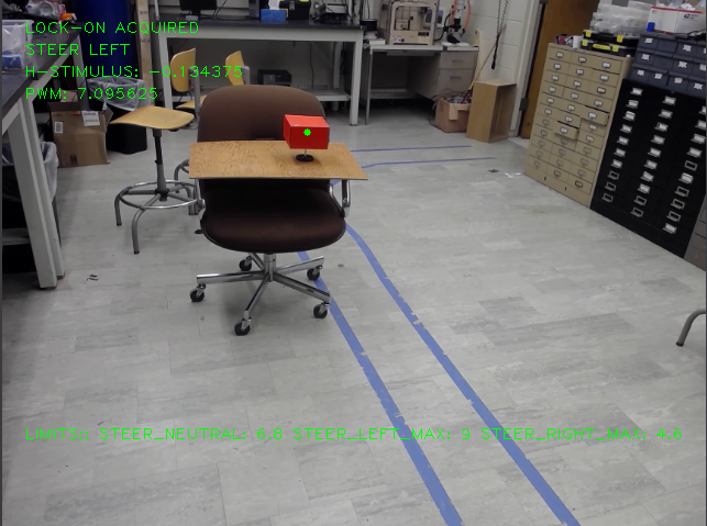
Fig.: Final tracking system locked-on to the red target. Note the generated steering response. 
Fig.: Classification of release stations. Note that the blank station in the back is filtered out as noise.
Project Demonstration
The Final Design: Our warehouse robot, with software and hardware development complete, proceeded to the testing phase in the form shown below.
THE PRELIMINARY DEMO: In the video below we see the forklift identifying the package (the red box) by its color and maneuvering over to it autonomously. We see the forklift lift the package as it begins the package drop off sequence.
THE FULL DEMO: In the video below we see the forklift identifying the target package (the red box), maneuvering to it autonomously, acquiring it, identifying the appropriate release station, maneuvering to it, and then releasing the package. Note that while a green release station is also present, the robot does not navigate to it as it does not match the red label of its acquired package.
We may reflect on the following:
- Arrival detection requires some tuning (namely adjusting the threshold value at which the robot determines its target to be ‘near enough’).
- Software PWM is sufficient but far from satisfactory.
- The drive motor is currently running under open-loop control. It is certainly possible to feed scaling data back to the controller (without anything fancy like Visual SLAM), in which case the robot could close the loop on its forward speed, not just its steering direction.
PROJECT CONCLUSION
THE RETROSPECTIVE: We delivered a minimum viable product: our warehousing solution is capable of detecting and classifying packages as specified and relocating them to their appropriate station.
The hardware and the software teams diligently pursued their duties in parallel, eventually converging in effort as the final demo drew near and the technical issues increased in complexity (e.g., the transmission had to be entirely replaced, the proportional controller frequently adjusted, and the ESCs occasionally reprogrammed).
In the end, we were able to tune our robot to a state in which all systems worked in concert (without failure) to demonstrate our project’s full potential.
The Future: Due to time constraints, there remain a few features that we were originally planning to support but ultimately did not. Our initial proposal (specified above) was to construct an autonomous forklift capable of sorting multi-colored packages to different release points. Furthermore, we wanted to use conventional palettes for our demonstration (though in practice, fork-alignment proved a significant challenge). Lastly, the original design included and made full use of an ultrasonic array to feature potential obstacle avoidance (our final product, while coming with a fully-installed ultrasonic array, only drives the front one–and only to initialization). We sketch out our list of potential improvements as follows:
Multiple Color Detection
- As of now, our forklift can actually detect two different colors of packages and release points (RED and GREEN). However, we decided to restrict the demonstration to a single-colored package because two guidance-related factors call for immediate improvement, detailed below:
PRECISION CONTROL
- The forklift performs closed-loop proportional control of the steering servo. Unfortunately, we never closed the loop on the drive motor. Once P-control (or perhaps even PID-control) is implemented on both the steering and the drive, the vehicle should theoretically be able to navigate with better fidelity.
- Another idea is adding alignment indicators to the palettes and forks. By checking for a parallel condition through the webcam feed, the robot may be able to align its forks with the target package from any approach angle.
OBSTACLE AVOIDANCE
- The four ultrasonic sensors mounted on the vehicle can detect objects in close proximity. Therefore, whenever an unforeseen hazard (such as a human being) is detected within some predefined range, we could interrupt the robot with an emergency stop protocol.
- Configuring two cameras in stereovision and installing a dedicated accelerator for visual workloads could enable the robot to perform SLAM. Among many other benefits, this would make possible the supervision and computation of far more complex trajectories.