People
Team Members
Team Sponsor
Molly Over
Project Mentor
Professor Christopher Muir
Abstract
The global transition to renewable energy is challenged by the intermittency of energy source outputs, such as solar and wind, that do not offer the same reliability as fossil-fuel based energy generation. Variability in this generation results in uncertainties for customers, especially during times of peak demand. MicroEra Power’s THERMAplus system offers a promising solution by providing efficient energy storage that allows customers to purchase electricity during times of low demand through the utilization of phase change material. The current system faces challenges with installation efficiency and overall layout. This project aims to redesign the system to be more mobile and standardized, optimize component layouts and improve the space efficiency. Advancements in these areas will facilitate broader adoption and ease the implementation of THERMAplus, supporting a more sustainable energy future.
Problem Definition and Overview
The shift to renewable energy is limited by the reliability of current sources, such as solar and wind. MicroEra Power’s THERMAplus system stores energy efficiently using phase change materials, helping customers buy electricity when demand and costs are low. Today, the system faces installation and layout challenges. Our project focuses on making it more modular, optimizing the component layout, and optimizing space efficiency to drive broader adoption and support a more sustainable energy future.
Requirements and Specifications
REQUIREMENTS
| REQUIREMENT NUMBER | DESCRIPTION |
|---|---|
| 1 | The modular design must allow for easy access to all critical components. Critical components include valves, heat exchangers and pumps. |
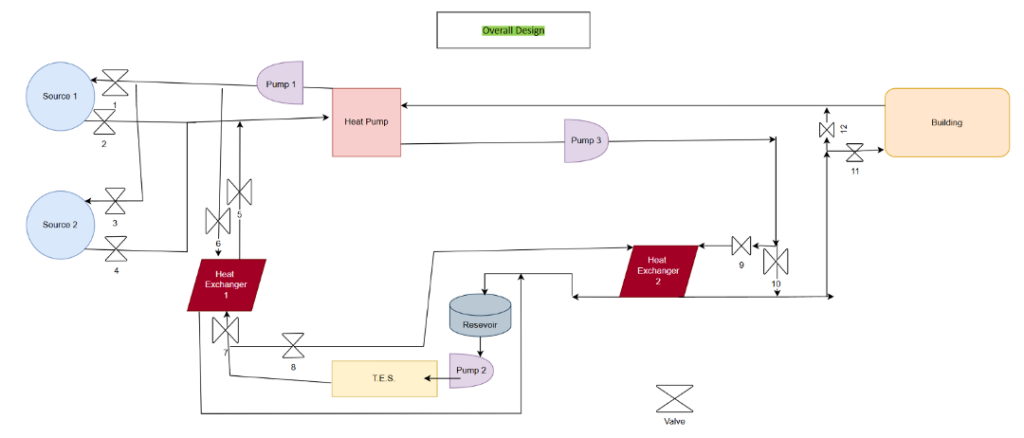
| 2 | The design must have 3 separate piping loops, one for the heat pump sources, one for the building connection and one for the thermal energy storage (TES). |
| 3 | The heat pump must have 2 sources for connection and use. |
| 4 | For the case of system operation with no TES, the building loop must be on the supply side of the heat pump and the TES loop on the source side of the heat pump. |
| 5 | For the case of system operation with TES as a source, the building loop must be on the supply side of the heat pump and the TES loop on the source side of the heat pump. |
| 6 | For the case of system operation with direct heating/cooling with the TES, the TES loop must exchange with the building loop. |
| 7 | For the case of system operation with the TES being charged, the TES loop must be on the supply side with sources on the source side of the heat pump. |
SPECIFICATIONS
| SPECIFICATION NUMBER | VALUE & UNITS | DESCRIPTION | METHOD OF EVALUATION |
|---|---|---|---|
| 1 | 48 inches | Maximum length allowed for system design (standard pallet dimension). | Tape measure |
| 2 | 40 inches | Maximum width allowed for system design (standard pallet dimension). | Tape measure |
| 3 | 72 inches | Maximum height allowed for system design. | Tape measure |
| 4 | 5% | An efficiency target for pump losses. Losses must be less than or equal to 5% of the total stored energy amount. | Spreadsheet calculation |
| 5 | 24 GPM | System flow rate quantity. Based on previous TES charging and discharging measurements. | Purchased product specification |
| 6 | 4 hours | Heat transfer discharge rate based on a 150-gallon volume TES system. | Computation |
| 7 | 8 hours | Heat transfer charge rate based on a 150-gallon volume TES system. | Computation |
| 8 | 3°C | Maximum temperature change allowed for the heat exchanger. | Purchased product specification |
| 9 | 3 feet | Piping connections to the TES system must be at least 3 feet above the base of the design. | Tape measure |
Design Analysis and Process
Our design process began with identifying key inefficiencies in the existing THERMAplus system, followed by concept development using sketches and Pugh matrices to compare configurations. We then built detailed CAD models, performed pressure drop and vibration analyses, and constructed a functional prototype to validate performance, accessibility, and modularity improvements.
CONCEPT DEVELOPMENT
Various concepts were explored to satisfy each heating, cooling and charging subcase and for optimal component layout. The diagram below shows the final 2D result after concept iterations.
PRESSURE DROP ANALYSIS
The total pressure drop for each of the circulating loops was calculated using Bernoulli’s principle and the Darcy-Weisbach equation. The analysis took into account pipe lengths and friction, resistance from fittings and turns, and height changes. This analysis informed each design iteration as the goal was to minimize pressure drop at 24 gallons per minute.
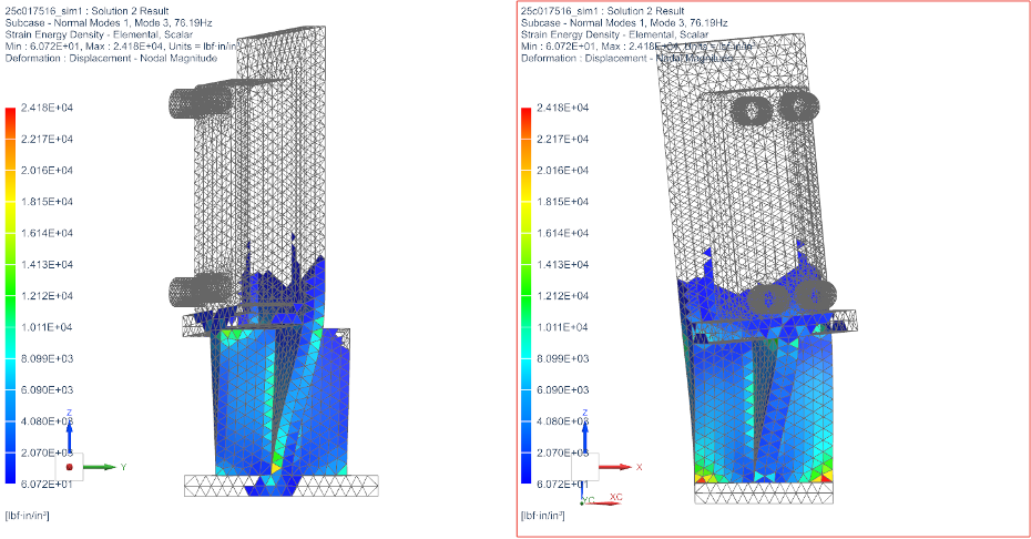
VIBRATION ANALYSIS
A vibration analysis on both of the heat exchanger stands and a critical pipe section was conducted to ensure that resonance would not occur. If one of the natural frequencies of the system matched the operational frequency of the pumps, resonance would be induced, which would likely lead to catastrophic failure due to fatigue.
Project Technical Challenges
Overall, the project presented several technical challenges, primarily centered around fabrication:
- Initial clamps used to connect PEX piping to associated fittings did not provide a tight enough seal, leading to leaks in system operation.
- The PEX piping proved to be very difficult to straighten, leading to issues with overall assembly and tolerances in the model.
- Lack of access to heating supply sources, not allowing for verification of heating components and overall function.
- The PEX piping loops required supports, which were assembled using PVC, ultimately providing greater stiffness in the system.
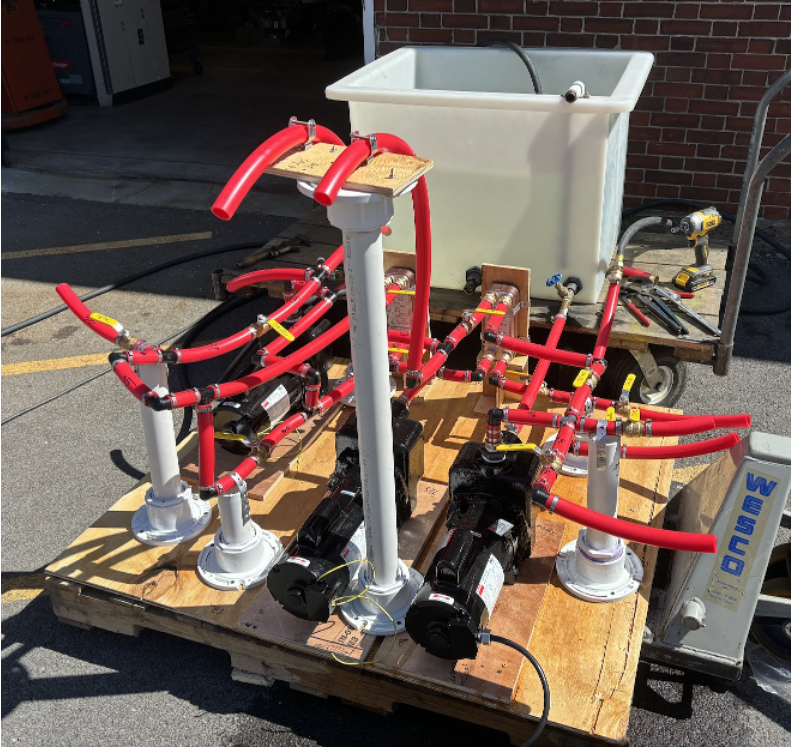
Project Result
The final design successfully met all of the project requirements and 7 out 9 specifications, resulting in a compact thermal energy storage system optimized for easier installation and maintenance. Key improvements included reduced pressure losses across all loops, improved component layout, and enhanced structural resilience validated through vibration and fatigue analysis in Siemens NX. A full-scale prototype was built and one of the piping loops was tested, confirming that the system could operate effectively. While the system did not meet the pump efficiency target or flow rate target due to limitations in motor performance, all other specifications, including size constraints, and heat transfer capacity, were achieved. This demonstrates the viability of the redesigned intermediate heat exchanging unit of the thermal energy storage system.
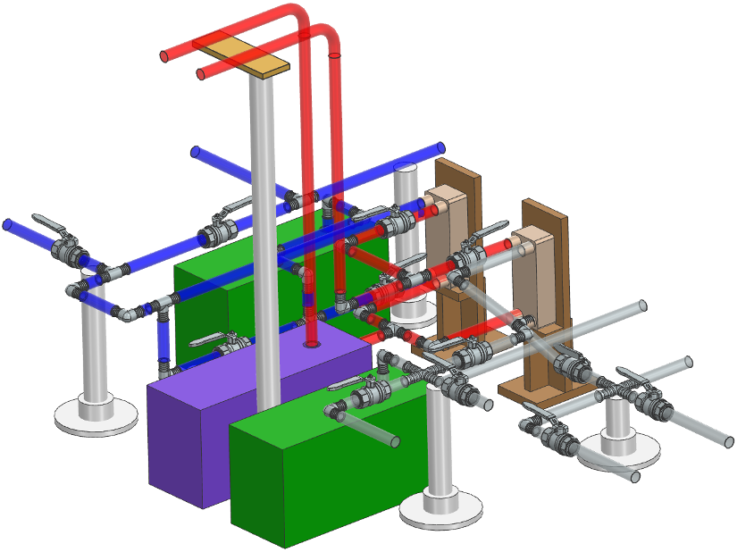
FINAL CAD MODEL OF SYSTEM
BUILD IN PROGRESS
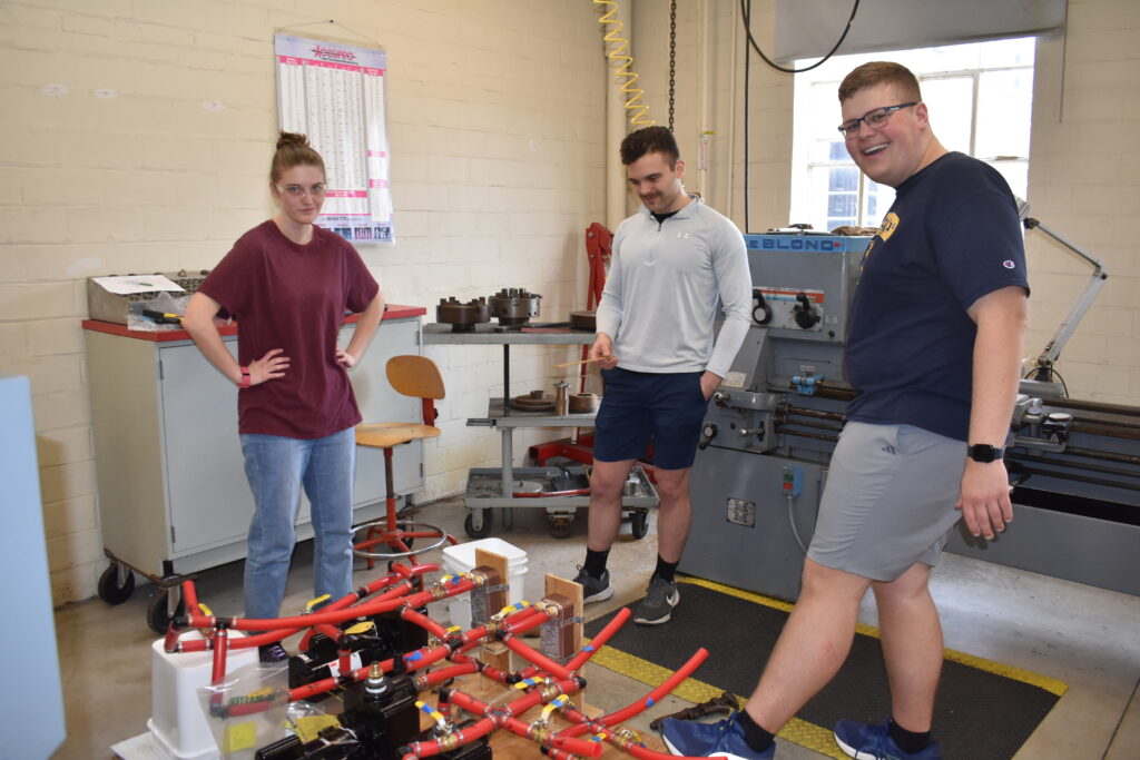
Building the system 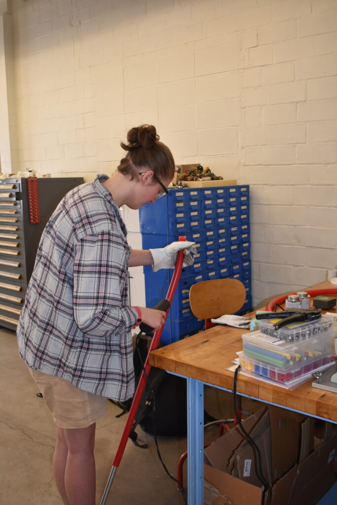
Straightening PEX 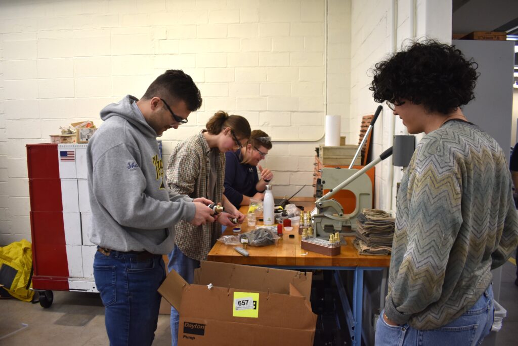
Wrapping fittings in teflon tape
FINAL BUILT MODEL OF SYSTEM
Final Design Report
Presentation Video
Presentation Slides
Acknowledgements
We would like to express our heartfelt gratitude to the many individuals whose support and contributions have been essential to the success of this project. A special thank you goes to our sponsor, Molly Over, whose generous sponsorship, valuable feedback, and mentorship guided us throughout the process. We are deeply grateful to Samantha Kriegsman for her unwavering assistance with our system components, and to Bill Mildenberger and Jim Alkins for graciously providing their workspaces and tools, without which our progress would have been much more difficult. Additionally, our appreciation extends to Chris Pratt and Alex Prideaux for their efficient handling of our system components, to Sebastian Gomez for his invaluable guidance as our TA, and to Professor Christopher Muir, whose dedication, wisdom, and mentorship have been the cornerstone of our success as engineers.