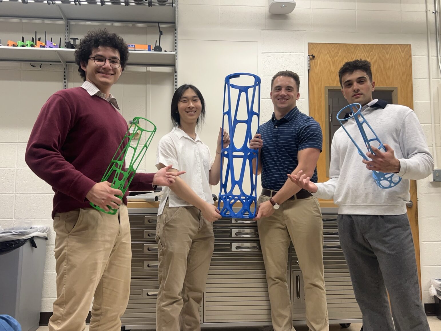
Listed from Left to Right: Marvin Calderon, Arden Gao, Jake Snyder, and Ethan Sanna
Team Members
- Marvin Calderon
- Arden Gao
- Ethan Sanna
- Jake Snyder
About the Team
Marvin
Marvin is a senior at the University of Rochester from Queens, NY, and is pursuing a B.S. in Mechanical Engineering. He also the president of the University of Rochester’s Society of Hispanic Professional Engineers chapter. For this project, he focused mostly on iterative design, simulation, and workflow optimization. He is passionate about research and development as well as engineering for extreme environments.
Arden
Arden is a senior at the University of Rochester from Irvine, CA, and is pursuing both a B.S. in Mechanical Engineering and a minor in Aerospace Engineering. Over the duration of this project, she focused on creating and modifying FEM setups and simulation environments to both rapidly iterate designs and ensure realistic conditions under which to validate analysis results. She is passionate about mechanical analysis and strives to enter the industry as a design engineer or finite element analyst.
Ethan
Ethan is a senior at the University of Rochester pursuing a B.S. in Mechanical Engineering from Westchester, NY. For this project, he focused on operations and material testing to improve model correlation and design reliability. He is passionate about mechanical design and is looking forward to beginning his career in the advanced nuclear industry this June.
Jake
Jake is a senior at the University of Rochester from Malvern, Pennsylvania, pursuing a B.S. in Mechanical Engineering with a minor in Electrical and Computer Engineering. Throughout this project, he focused on concept development, preliminary analysis, manufacturing planning, vendor outreach, and full-scale prototype preparation. He is interested in mechanical design, robotics, and testing and validation, especially as they apply to complex problems.

Sponsors

L3Harris Team
- Patrick Ellsworth (Director, Chief Engineer – Exquisite Imaging Systems, Space Superiority)

- Pat Zinter (Systems Engineering Manager, Aerospace)

- Steve Sutton (Staff Engineer – Metal Additive Manufacturing)

- Devin Woodyard (Specialist, Mechanical Engineer)

Abstract
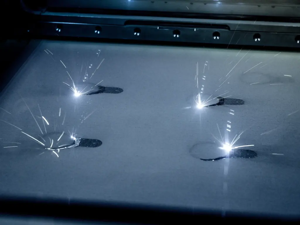
Additive manufacturing (AM) is increasingly being used in aerospace applications because it enables complex, lightweight geometries that are difficult or impractical to produce using traditional subtractive manufacturing. This project, sponsored by L3Harris, focused on the design, analysis, and prototype development of an additively manufactured forward metering structure (FMS) for a space-based optical imaging system. Additive manufacturing is advantageous as it allows for “economic efficiency, unparalleled design freedom, high customizability… and the ability to process a wide range of materials including metals” [Mohan, D. G., A, S., S, G., Jatti, V. S., S, K., and R, M. K., 2026, “Additive Manufacturing for Space Applications: A review of materials, methods, and future frontiers,” China Welding, 35(1), p. 100010.]. The FMS serves as the structural element that supports and positions the secondary mirror (SM) above the primary mirror (PM), making stiffness, alignment stability, thermal performance, vibration resistance, mass efficiency, and optical obscuration critical design considerations. Throughout the project, the team has developed and evaluated multiple design iterations using hand calculations, CAD modeling, finite element analysis (FEM), material testing, vendor and sponsor manufacturability feedback, prototype fabrication, and physical testing. The team worked closely with the team at L3Harris, Professor Christopher Muir, and the University of Rochester’s Mechanical Engineering department to simulate several iterations, test and validate materials, manufacture and construct a prototype, and successfully provide L3Harris with a final design. This website documents the design process, analysis methods, prototype development, testing, and final recommendations provided to L3Harris.
Project Details
Problem Definition
The purpose of this project is to design and fabricate a 3D metal-printed forward metering structure (FMS) to connect and align the primary and secondary mirrors for a space-based optical satellite system. L3Harris has requested a design optimized for additive manufacturing to reduce build time while maintaining critical structural performance. This process allows the FMS to be fabricated as a monolithic part in a single build cycle, rather than as a complex multi-component assembly. This approach also encourages the team to incorporate advanced geometries that would not be practical with common manufacturing techniques but could be easily achieved with 3D printing. It’s important to recognize that modest performance trade-offs will take place; however, the purpose of this project is to demonstrate a fast, repeatable, and cost-effective solution for the future of space-based technologies. The team’s final deliverable will consist of a tested prototype and correlated model that meets industry requirements.
Requirements and Specifications
Requirements
- [UR-FMS-004] The FMS shall define a clear, traceable primary load path from the Secondary Mirror interface to the AMS interface. All major load-bearing members shall be identified in the structural model and correlated to physical geometry.
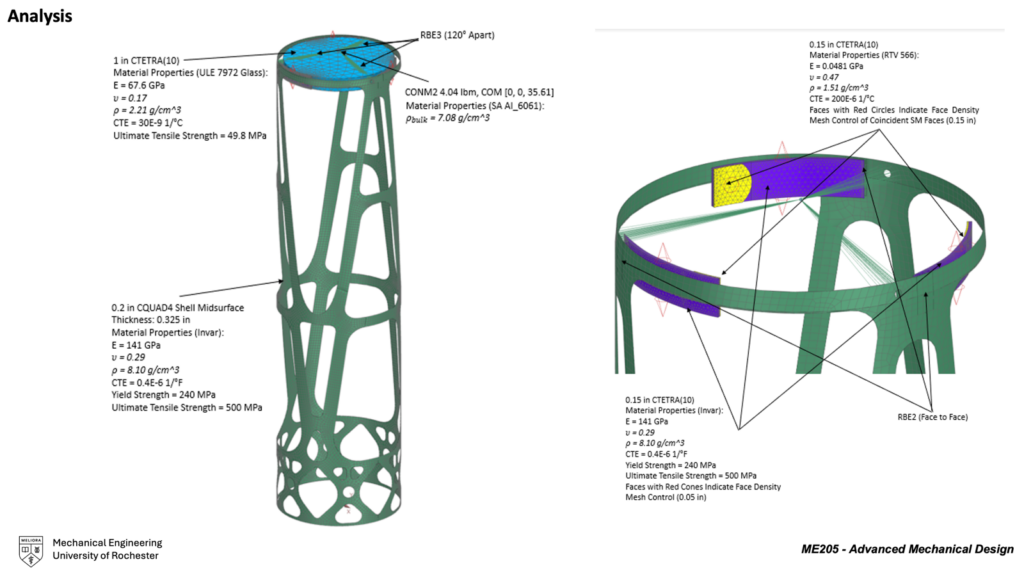
- [UR-FMS-005] The FMS material shall be Invar (or an Invar-class alloy) to minimize coefficient of thermal expansion (CTE) driven misalignment. (See Overview document for values)
- [UR-FMS-010] The FMS should incorporate redundancy or fault-tolerant load paths where required by mission assurance analysis, such that no single credible structural failure results in loss of SM containment or gross misalignment.
- [UR-FMS-011] The FMS shall be produced using additive manufacturing. The design shall incorporate controlled additive manufacturing process parameters sufficient to support topology and lattice optimization, model-to-test correlation, thermal stability characterization, and repeatable manufacturability.
- [UR-FMS-012] The FMS shall be designed to print vertically with the AMS interface side on the build plate. Support structures are permitted but undesirable; any required supports shall be limited to non–optical-critical surfaces and shall be fully removable without damage to functional interfaces.
- [UR-FMS-013] The FMS shall be designed to ensure there are no trapped cavities or unvented volumes that could retain contamination, inhibit precision cleaning, or create pressure differentials.
- [UR-FMS-014] The FMS shall include handling features or zones to support safe lifting, fixturing, and inspection without imparting loads through optical interfaces. (These features will likely need to be near the AMS interface, below the primary mirror)
- [UR-FMS-015] For any hollow-shell or lattice designs, the FMS shall include contamination control features (e.g., vent mesh) to prevent debris migration to optical surfaces and shall permit inspection and verification of these features.
- [UR-FMS-016] The FMS shall define and maintain a controlled datum scheme and provide metrology features enabling repeatable measurement of SM position relative to the AMS.
- [UR-FMS-017] The FMS shall define interfaces for the following hosted hardware.
- [UR-FMS-018] The FMS should recommend routing and mounting locations for thermal hardware associated with the Secondary Mirror (SM) and shade assembly (Heater tapes, thermistors, cabling) while maintaining defined optical and baffle keep-out zones.
- [UR-FMS-019] All FMS surfaces visible to the optical cavity shall meet stray-light requirements, including low-reflectance finishes, non-flaking coatings, and avoidance of specular glint paths to the focal plane.
Specifications
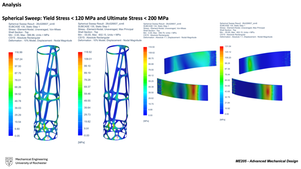
- [UR-FMS-001] Quasi-static launch loads of a 30 g spherical sweep, swept at 15-degree increments, while supporting all hosted hardware. Launch loads shall be combined with a 5°C to 35°C temperature range.
- [UR-FMS-002] Factors of Safety (FOS)
- Yield ≥ 2.0
- Ultimate ≥ 2.5
- Ultimate Glass ≥ 5
- Buckling ≥ 4.0
- If a micro-yield criterion is used, the criterion shall be defined (e.g., strain-based), and the micro-yield factor of safety shall be ≥ 1.0 for all applicable load cases.
- [UR-FMS-003] Under a 1°C isothermal temperature change, the average motion of the SM interface shall be limited to:
- 0.2 µm (7.87 micro inches) translation (RSS of X and Y), and
- 0.9 µrad rotation (RSS of Rx and Ry)
- [UR-FMS-006] Mass < 25 lbm, inclusive of structural material and permanently attached features, and exclusive of hosted hardware. The following mass growth allowances shall be applied for design gate reviews:
- Concept design: 20%
- Preliminary design: 15%
- Final design: 10%
- Post–Final Design: 5%
- As-built measured hardware: 0.10%
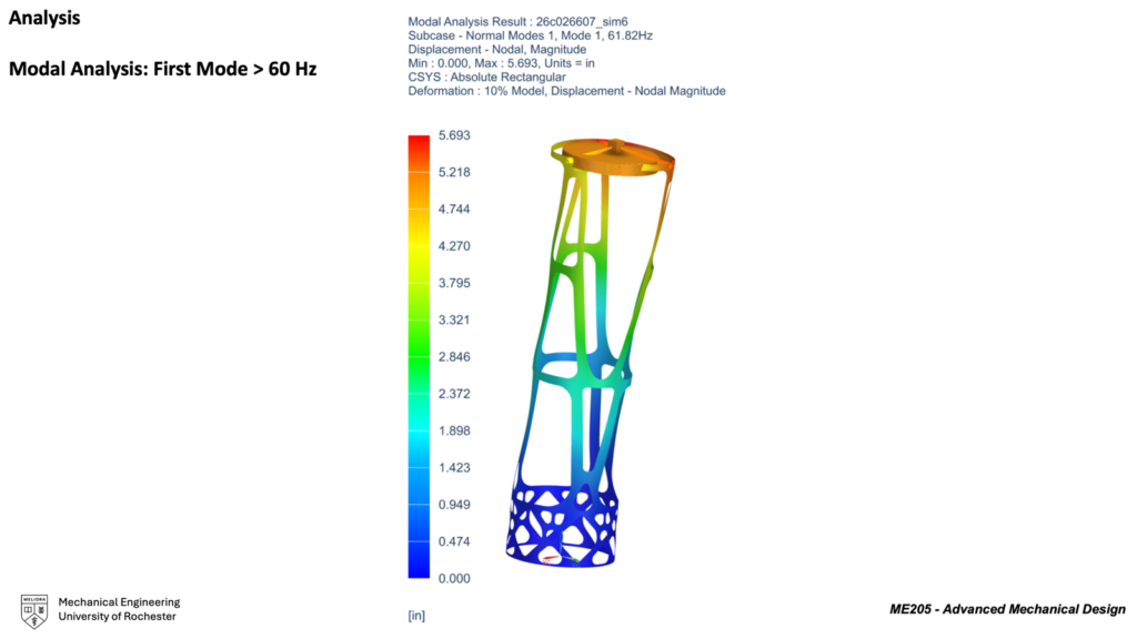
- [UR-FMS-007] First structural mode of the FMS shall be 60 Hz or greater (greater than 100 Hz desired) when constrained at the AMS interface and supporting all hosted hardware, including representative joint stiffness and preload assumptions. (See MICD for detailed weights)
- The AMS interface is defined as being 35” from the back side of the Secondary Mirror (SM)
- Explicitly document assumed joint stiffness, boundary conditions, and interface preload values at the AMS and SM interfaces. Sensitivity of the first mode frequency to joint stiffness assumptions shall be assessed.
- [UR-FMS-020] The FMS shall have a maximum of 22% total obscuration area of the entrance pupil of the Primary Mirror (PM) (assuming a 0.8m diameter clear aperture). (Compliance may be demonstrated using geometric ray-blocking diagrams and projected area calculations; optical modeling is not required)
| Requirement ID | Description |
| [UR-FMS-001] | Quasi-static launch loads of 30 g spherical sweep, swept at 15-degree increments, while supporting all hosted hardware. |
| [UR-FMS-002] | Factors of Safety (FOS) •Yield ≥ 2.0 •Ultimate ≥ 2.5; •Ultimate Glass ≥ 5 •Buckling ≥ 2.5 |
| [UR-FMS-003] | Under a 1°C isothermal temperature change, the average motion of the SM interface shall be limited to: •0.2 µm (7.87 micro inches) translation (RSS of X and Y), and •0.9 µrad rotation (RSS of Rx and Ry) |
| [UR-FMS-006] | Mass < 25 lbm |
| [UR-FMS-007] | First Mode > 60 Hz |
| [UR-FMS-020] | Obscuration < 22 % |
Project Highlights
Initial Design Concepts
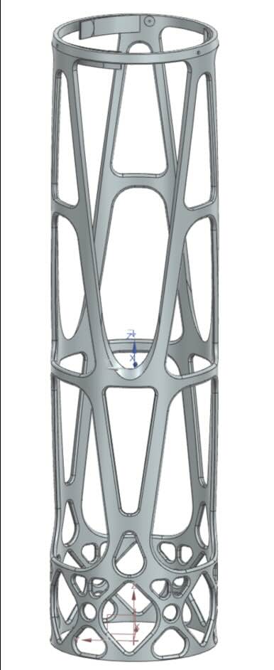
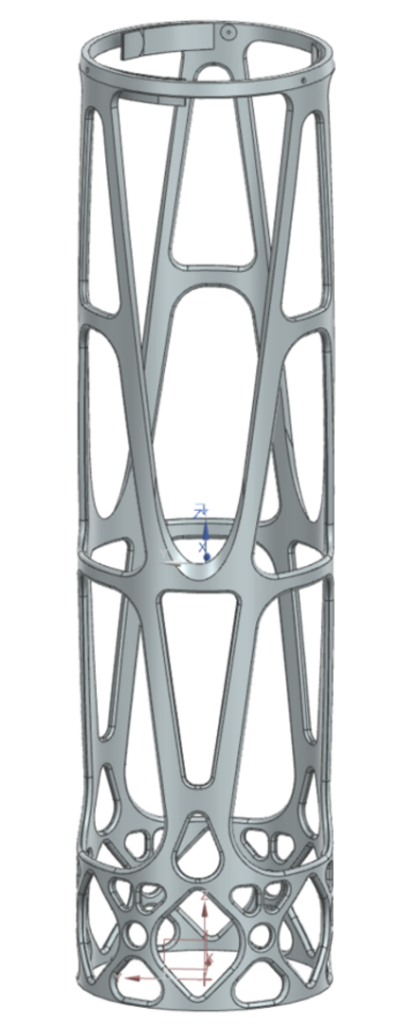
Leading up to the Preliminary Design Review (PDR), the design process involved creating approximately 20 initial computer-aided design (CAD) concepts to narrow down to a final, optimized selection. This phase was driven by a rigorous “fail-fast” technical feedback loop, in which designs that failed to meet the performance requirements outlined above were either dropped or improved. This process falls in line with the design philosophy presented by L3Harris: “Fast. Forward.” The following three concept designs are the product and stand on the shoulders of numerous iterations and improvements.
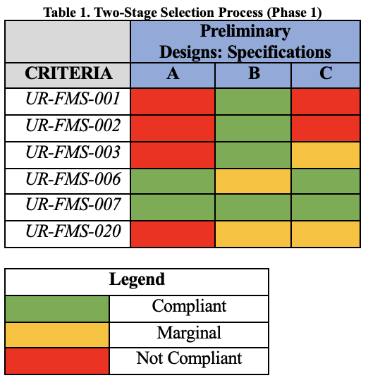
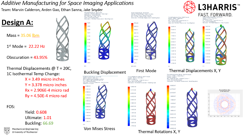
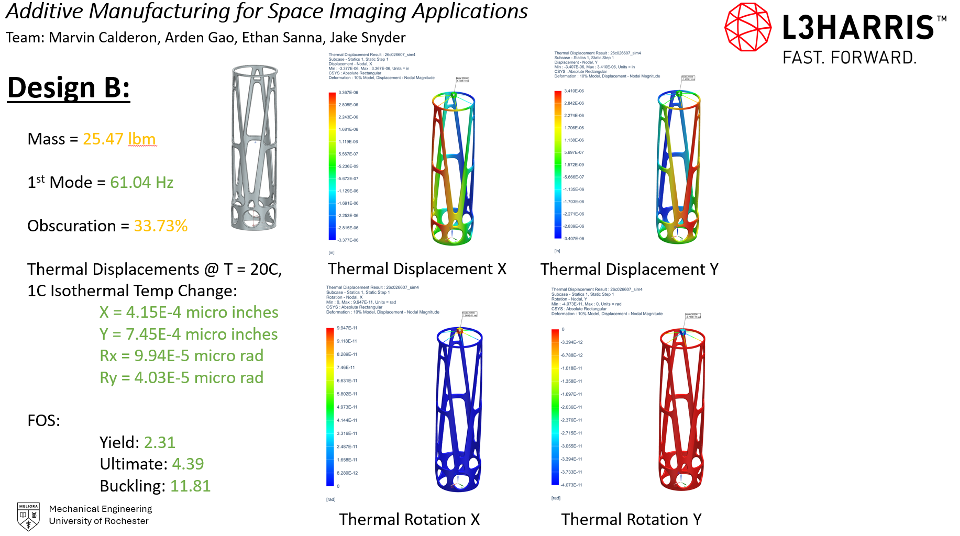
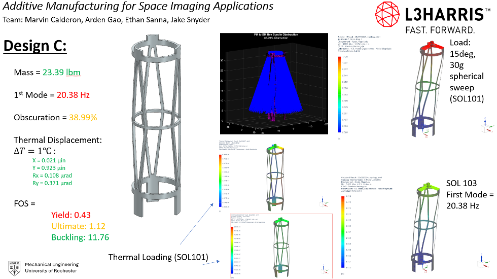
The three designs were evaluated in a two-stage selection process: a technical compliance screening and a comparative outlook. This process is exhibited in Table 1. In the first stage, the three designs were first individually evaluated against six L3Harris technical specifications. It’s important to note that none of the designs selected were able to meet all the rigorous specifications. However, this process showcased which design was the closest and could be improved to satisfy all constraints. The design that adhered to the most specifications was designated as the technical baseline. In the second stage, the three designs were compared against subjective metrics determined by the team. This included manufacturability, complexity, improvability, and design maturity. These four categories have been part of the team’s thought process since the beginning of the project. The baseline design would compare against the other two in these categories, and the design with the highest cumulative performance would be selected as the design moving forward. This is a classic example of the down-selection methodology presented by L3Harris.
Ultimately, this process resulted in the team selecting Design B. This design met four out of six specifications and had the highest cumulative total across the subjective criteria. From this point on, the team refined Design B to comply with specifications [UR-FMS-006] and [UR-FMS-020]. Additionally, an interface between the FMS and the SM using flexures was designed to meet these specifications.
Full-Scale ABS Prototype, Testing, and Correlation
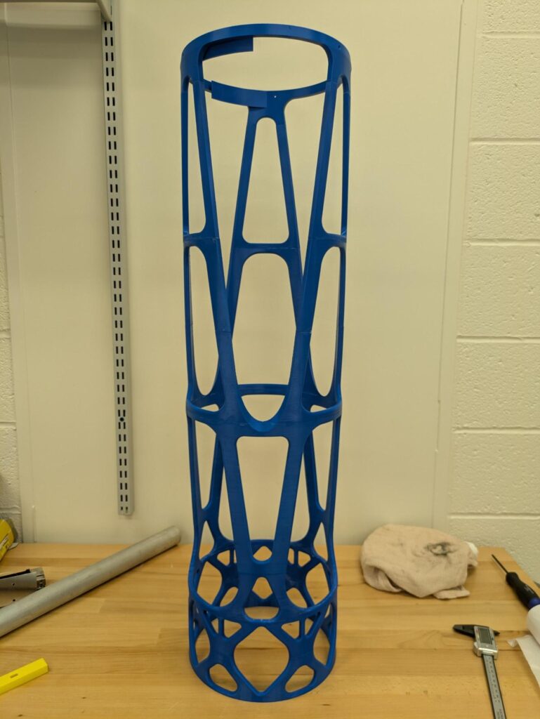
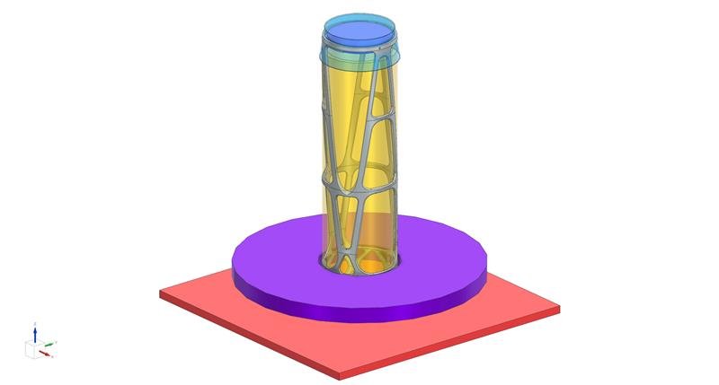
To support model correlation and physical validation of the design, the team produced a full-scale representative prototype of the forward metering structure (FMS) using 100% infill ABS on a Stratasys F270 printer in the University of Rochester’s Rettner Hall workshop. Because finite element optimization and CAD refinement continued late into the design process, the printed prototype was based on one of the final major design iterations and differed slightly from the exact final geometry. Since the full-scale FMS exceeded the build volume of the F270, the structure was divided into multiple sections, printed separately, and bonded together, with printed ABS dowels used at the interfaces to improve alignment during assembly. This approach allowed the team to preserve the full-scale geometry, major load paths, interface locations, and overall optical openness of the design while staying within the project’s schedule, budget, and equipment constraints. Rettner Shop Manager, James Alkins, served as a primary point of contact throughout the process and provided key support with print planning, fabrication, and post-processing.
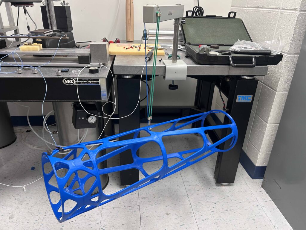
After manufacturing, to support model validation, the team performed vibration testing on the full-scale 3D printed ABS prototype of the forward metering structure. This testing was conducted to compare the behavior of the physical prototype against the team’s NASTRAN finite element simulations, as requested by L3Harris. The prototype was suspended horizontally using three bungee cords to approximate a free-free boundary condition, and an accelerometer was attached to the structure using beeswax while the prototype was excited with a calibrated impact hammer. From this test setup, the team measured a first mode frequency of 46.5 Hz.
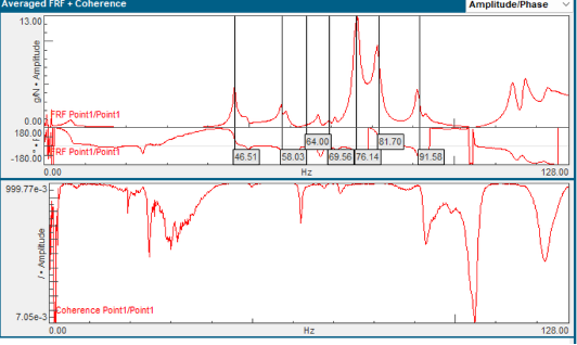
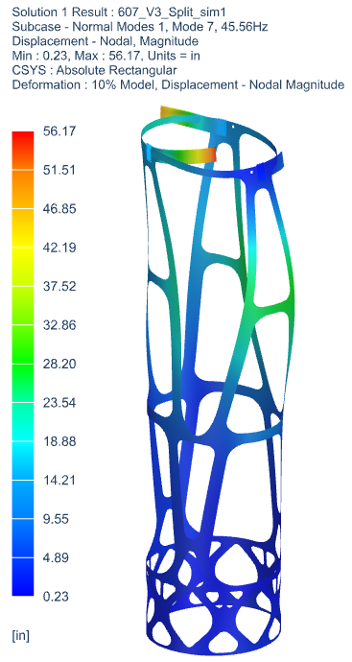
To correlate the physical test with simulation, the finite element model was updated to use experimentally measured ABS properties, including a prototype density of 0.971 g/cm³ based on the actual printed part mass. A corresponding free-free SOL 103 modal analysis was then run in NASTRAN, which predicted a first mode of 45.56 Hz. This resulted in an error of only about 2%, representing a strong correlation between the physical prototype and the analytical model. The small remaining difference is likely due to practical differences between the idealized simulation and the real prototype, including the sectioned and bonded nature of the print, varying print orientations between sections, and simplifications made in the shell-based FEM geometry. Overall, this correlation provided strong confidence in the team’s analysis approach and supported the validity of the broader mechanical model used throughout the project.
Why does this matter?
Societal Impact
This project supports the broader class of space-based optical systems used for weather forecasting, disaster monitoring, environmental tracking, and agricultural planning. Although the forward metering structure is only one subsystem, it helps enable the structural and thermal stability required for precise optical alignment and reliable data collection.
Economic Impact
A major goal of the project was to explore a faster, more repeatable manufacturing approach through metal additive manufacturing. While powder-bed fusion can be expensive per part, it offers long-term value through reduced part count, lower assembly complexity, faster iteration, and the ability to produce complex monolithic aerospace hardware without conventional tooling.
Environmental Impact
Metal additive manufacturing offers both advantages and tradeoffs. It can reduce assembly steps and enable lightweight, optimized structures, but it is also energy-intensive and depends on specialized feedstock and post-processing. Future improvements could focus on reducing support material, minimizing printed mass, improving powder removal, and making the design more efficient to manufacture.
Final Prototype Design and Performance
After down-selecting from roughly 20 early CAD concepts, the team refined a single baseline design through iterative finite element analysis, light obscuration studies, flexure-interface development, and additive-manufacturing-focused design changes. The final geometry was driven by structural and thermal performance requirements, printability constraints for metal additive manufacturing, and the tight optical envelope imposed by the system. By the end of the project, the final design successfully met five of the six key sponsor specifications, including structural safety, thermal stability, mass, and first-mode frequency. The one unmet specification, optical obscuration, proved to be an unusually difficult and highly coupled design challenge; however, L3Harris acknowledged this tradeoff and ultimately granted a formal waiver, prioritizing compliance with the first vibrational mode requirement due to its importance for surviving the launch environment. As a result, while the final design was not fully compliant in the strictest sense, it was accepted within the scope of the project and represents a result the team is extremely proud of, given the technical demands of the problem and the progress made over the course of the semester. In parallel, the team also fabricated and tested a full-scale ABS prototype to support manufacturability assessment and model-to-test correlation. Additional details on final compliance, analysis results, and prototype performance are provided in the figures below and in the Final Design Review document in the Supplementary Documents section.
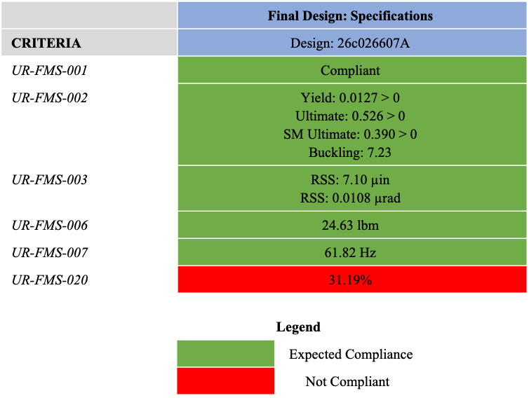
Future Work
If the team had more time or the opportunity to revisit the project, the highest priority would be further reducing optical obscuration to meet the final requirement. Although obscuration was a major focus throughout the design process, the final design exceeded the requirement by just over 8%, and meeting that target would likely require additional fine-tuning, optimization, and redesign using the team’s developed MATLAB tools together with continued NX-based refinement. Future work would also focus on leaning further into additive manufacturing by introducing more non-uniform member sizing, aligning structural members more closely with light paths, and reducing support-structure needs by minimizing 90-degree overhangs. In addition, a more representative prototype would ideally be produced using DMLS in Invar or a similar metal, since the ABS prototype used for model correlation was valuable for testing but does not fully reflect the material behavior or manufacturing method of the intended final system. Together, these next steps would move the design closer to full compliance while also improving manufacturability and test realism.
Acknowledgments
The ME205 L3Harris Senior Design Team would first like to thank our sponsor, L3Harris, and the team members, Patrick Ellsworth, Steve Sutton, Devin Woodyard, and Pat Zinter, for their technical expertise and support. The authors would also like to acknowledge and thank Professor Christopher Muir, along with Jim Alkins, Chris Pratt, and Angel Bermudez, for their mentorship and guidance throughout this semester. Finally, the authors would like to thank our peers in senior design, who have now been our classmates for the past four years in Mechanical Engineering at the University of Rochester. This project would not have been made possible without their willingness to share ideas, constructive feedback, and insight.