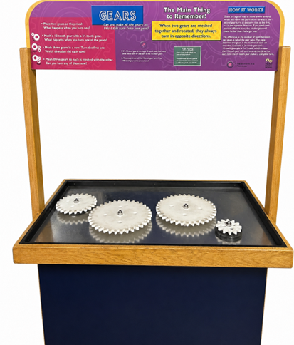
The How Things Work exhibit at the RMSC currently falls short of effectively demonstrating key mechanical concepts such as gear ratios change in direction of motion, and transmission of power. Thus project proposes a redesign to improve interactivity and educational opportunity to patrons of the museum.
Team Members


Abstract
The Rochester Museum and Science Center (RMSC) is currently undertaking an endeavor to upgrade it’s “How Things Work” exhibit. One of the subjects of this exhibit was the explanation of how gears work. The goal of this project was to improve on the existing design, focusing on immersion and explaining the underlying scientific principles.
The project went through three stages of prototyping and testing. The first prototype was rudimentary, meant as a proof of concept. The second prototype improved on several key aspects of the first, based on qualitative data taken at RMSC, but was ultimately very similar. The third prototype was a complete redesign, incorporating advanced manufacturing, sturdier materials, and integrated components.
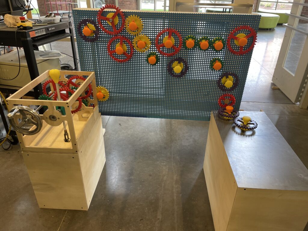
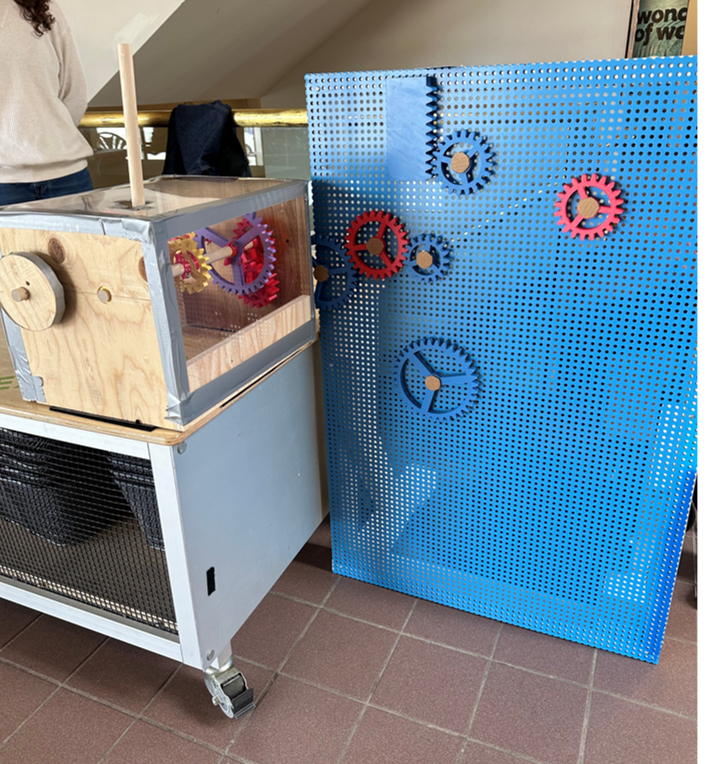
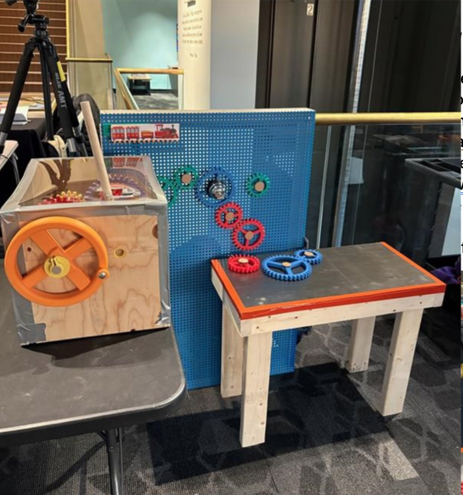
The final design consists of a magnetic “play wall” where free-spinning “play gears” could be attached and arranged, in addition to a transmission box which allowed the patron to select from two different speeds, and several “output” components such as a “record player” which demonstrated change in rotational speed by playing a song at various speeds.
Problem Statement
The current “How Things Work” gears exhibit at RMSC does not effectively demonstrate key mechanical concepts such as gear ratios or changes in motion direction. RMSC assigned a task to redesign the gears exhibit for a target audience of adults visiting with children ages 5-15. This project redesigns the exhibit to enhance interactivity through a transmission system and dual play surfaces, including a rack-and-pinion feature and a rotating record player mechanism. The improved design enables users to better understand how gears modify speed, direction, and power through hands-on learning.
Deliverables, Requirements & Specifications
Deliverables
| 1. Initial Design Plan |
| 2. Stage 1 Prototype |
| 3. Stage 1 Testing Data |
| 4. Iteration Design Plan |
| 5. Label Copy Prototype |
| 6. Stage 2 Prototype |
| 7. Stage 2 testing Data |
| 8. Final Stage 3 Prototype |
| 9. Final Label Copy |
| 10. Final Technical Design Report |
| 11. Poster |
| 12. User Manual |
Requirements
| 1. Engaging for adults visiting with children between the ages of 5 and 15. |
| 2.The exhibit should allow users to explore multiple outcomes based on their choices. |
| 3. Maintains functionality when incorrectly used. |
| 4. Designed in a way that considers the safety and accessibility standards of RMSC/Boston Museum of Science. |
| 5. Teaches an engineering subject in a way that the majority of visitors may understand or learn from. |
Specifications
| 1. Exhibit must fit through a standard double doorway. |
| 2. Moveable components (e.g. gears) cannot exceed 2.5 lbm. |
| 3. Interactive depth cannot exceed 20 in. |
| 4. Interactive height cannot exceed 48 in. |
| 5. The exhibit must be able to assemble and disassemble in 2 hours. |
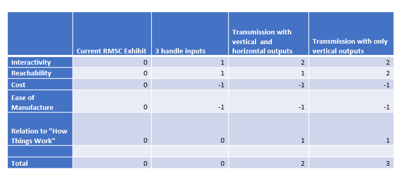
Concept & Pugh Matrix
Multiple solution concepts were developed during the planning stage of the project. Following the original demonstration, each design incorporated common elements, most notably magnetic “play gears” that users could reposition anywhere on a metallic play surface. The primary differences between concepts were the input mechanism, output components, and the placement and orientation of the metallic surfaces.
Prototype 1
Design & Fabrication
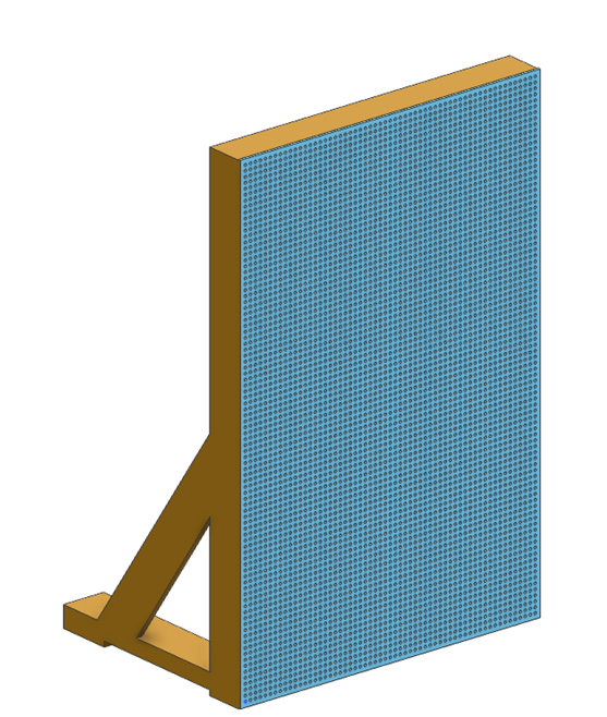
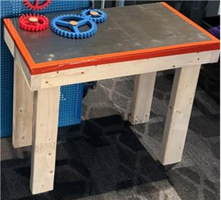
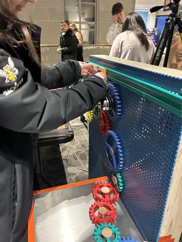
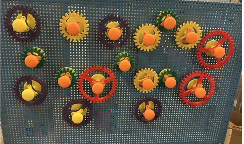
Play Wall
The metal play wall sized 30″x46″, 1/4″ thick was sourced from RMSC. 2×4 pine lumber was used to construct a frame for the metal surface.
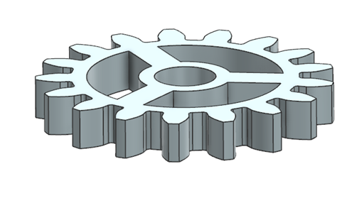
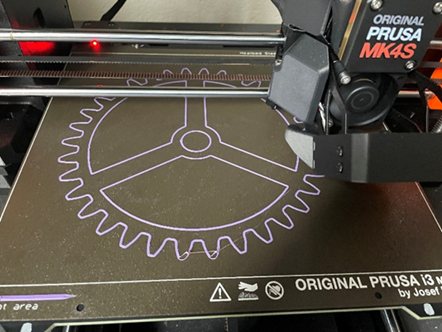
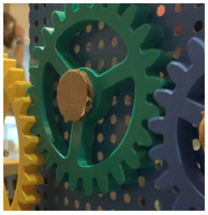
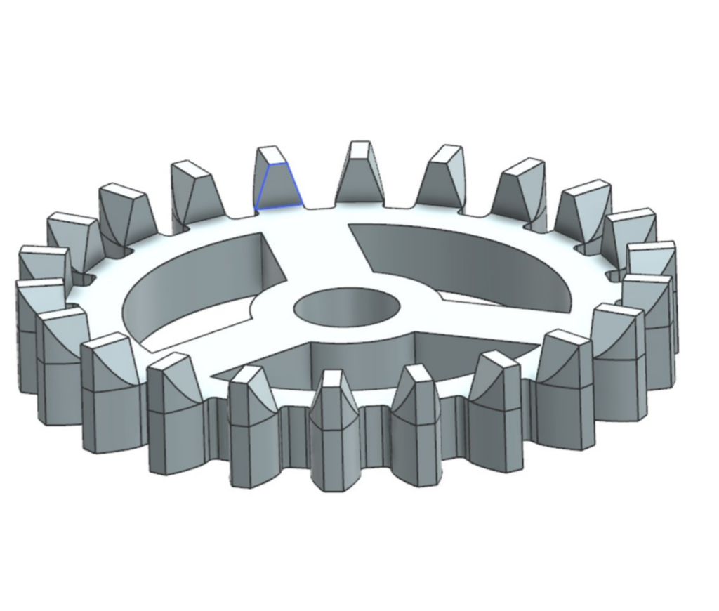
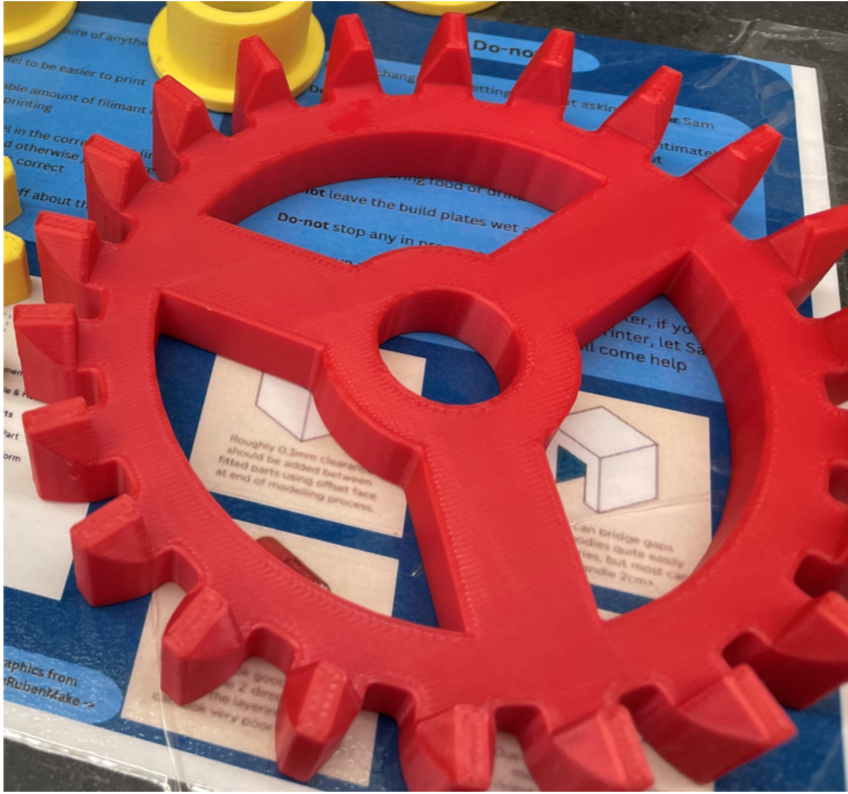
Gears
3D printed PLA gears were created using the gears plug-in in Siemens NX. A ¾” dowel was added through the center hole acting as the shaft for the gear to rotate around. A cardboard cap was then added to the top to prevent the dowel from shifting, while a washer with 6 weak magnets in an array were attached to the bottom.
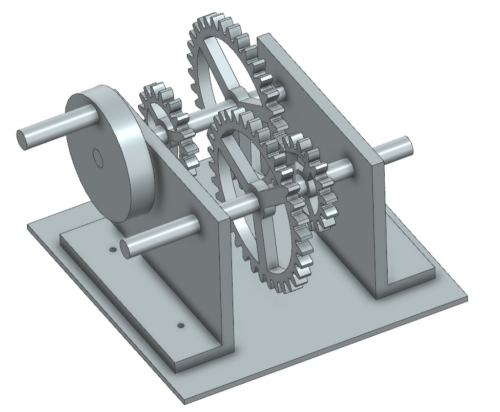
Transmission
The two speed transmission was created using the same 3D printed gears and dowel shafts. The faceplates were cut from ¾” Plywood, while the gears and shafts were secured by 3D printed clips and bearings.

Testing
The main goal for the first round of testing was to evaluate how intuitive the design was to the target audience. It was found that there were several mechanical issues with the design, including excess friction in the play gears and transmission, and lack of strength in some of the 3D printed components. Plans for the second prototype mostly included improving the ergonomics and adding outputs.
Prototype 2
Design & Fabrication
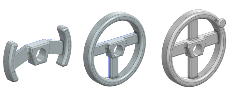
Hand Wheels
Three wheel designs were created in NX and 3D printed out of PLA, one that resembled a F1 steering wheel, a standard steering wheel, and one a peg wheel.

Horizontal Surface & Crown Gear
An additional magnetic surface was simply fabricated from sheet metal with a pine 2×4 base. The edges were taped over to remove the sharp edge. In order to allow the gears from the vertical surface to mesh with the horizontal surface, a crown gear was designed and 3D printed. This gear can mesh with regular spur gears that are in the same plane and in a plane set at 90°, which allows the two surfaces to be joined together.
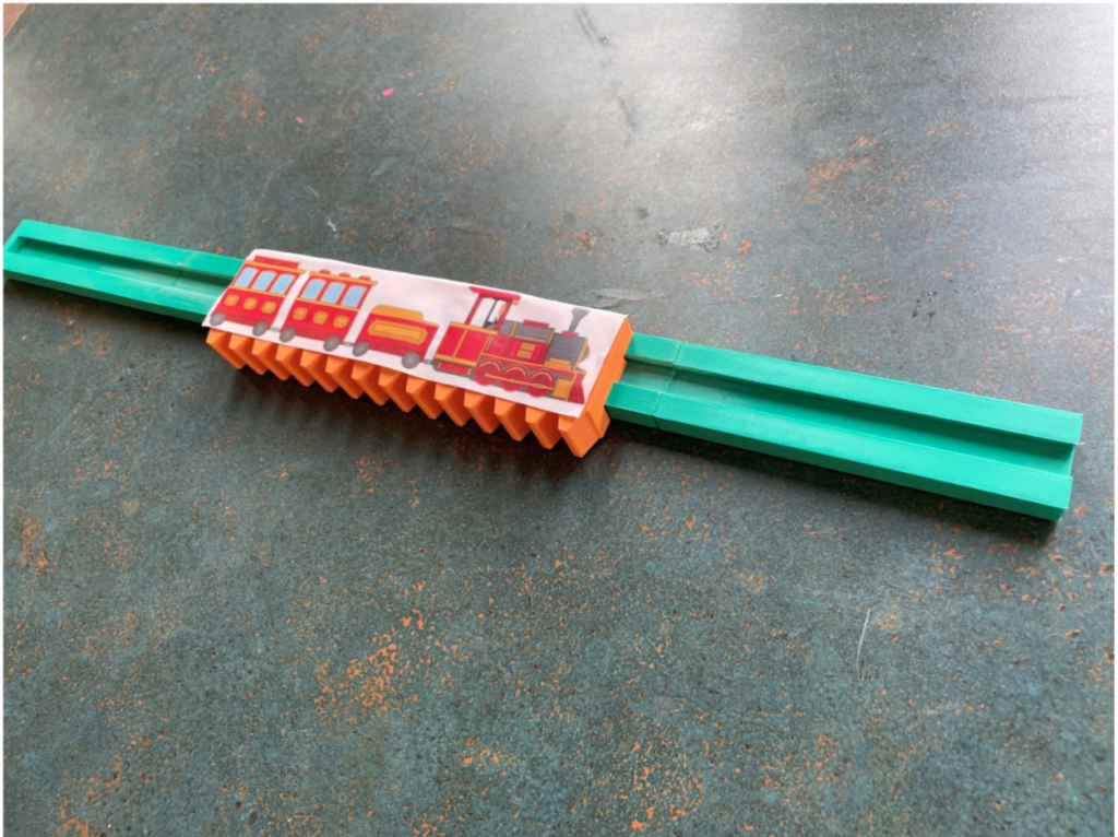
Rack and Pinion
A longer rack rail was added to the play wall, consisting of several 3D printed components glued together. Any of the play gears were able to act as pinions, moving the rack linearly along the rail.
Testing
For the second testing session, we wanted to test our hand wheel designs, as well as the reliability of the horizontal surface and crown gear, and the strong magnets. We found that the peg wheel design was the best suited for suggesting continuous rotation to the patron. We also observed that patrons didn’t realize that the play gears were meant to be picked up and moves around. Our plans for the final prototype were mostly concerned with once again upgrading our materials, as well as introducing design elements to help direct the patron, such as label copy and specific colors to indicate play objects.
Prototype 3
Design & Fabrication
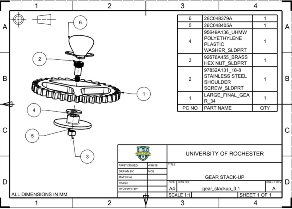
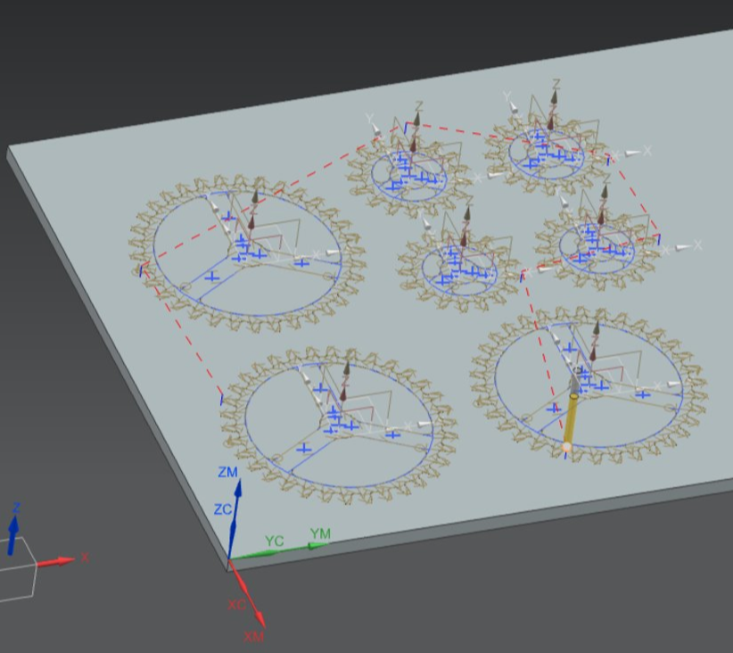
Play Gears
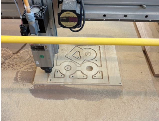
The play gear stack up was redesigned with stronger magnets, a 3D printed base, and a shoulder screw to hold the assembly together. The play gears were fabricated from 1/2″ baltic birch plywood cut on the CNC Shopbot mill.
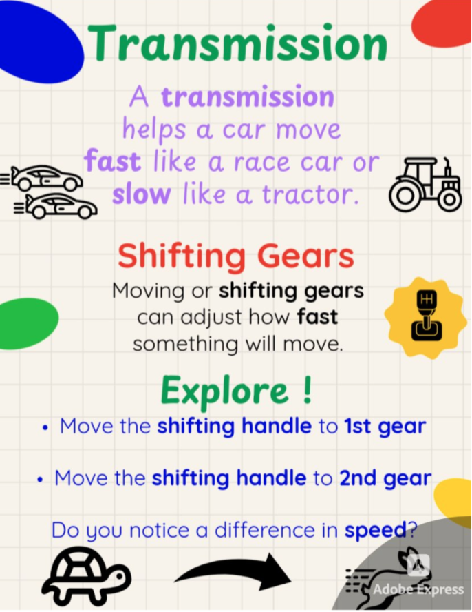
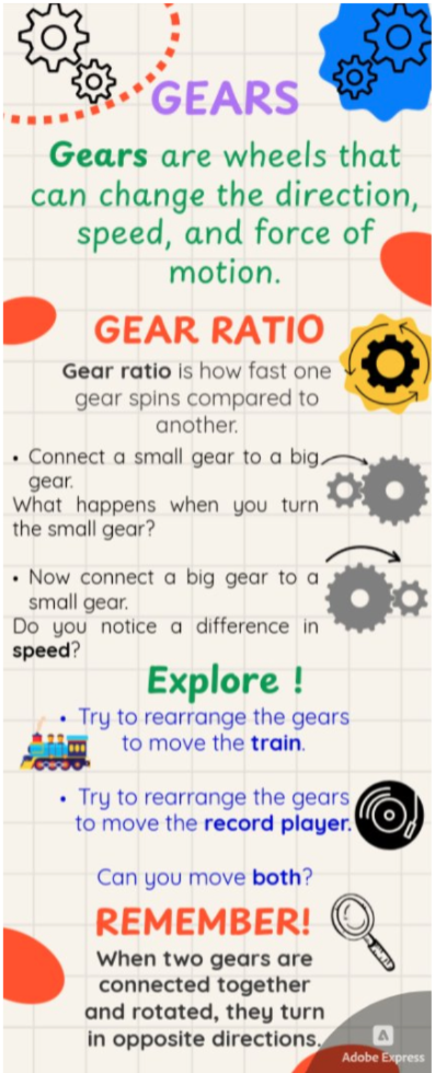
Label Copy
One of the main goals of the final prototype was to develop signage to help patrons learn from the exhibit. The label copy went through two rounds of iteration, using the website Hemmingway and feeback from out sponsor to revise, based on the RMSC style guide. The colors were chosen to match those used in the rest of the exhibit, and certain words were bolded for emphasis.
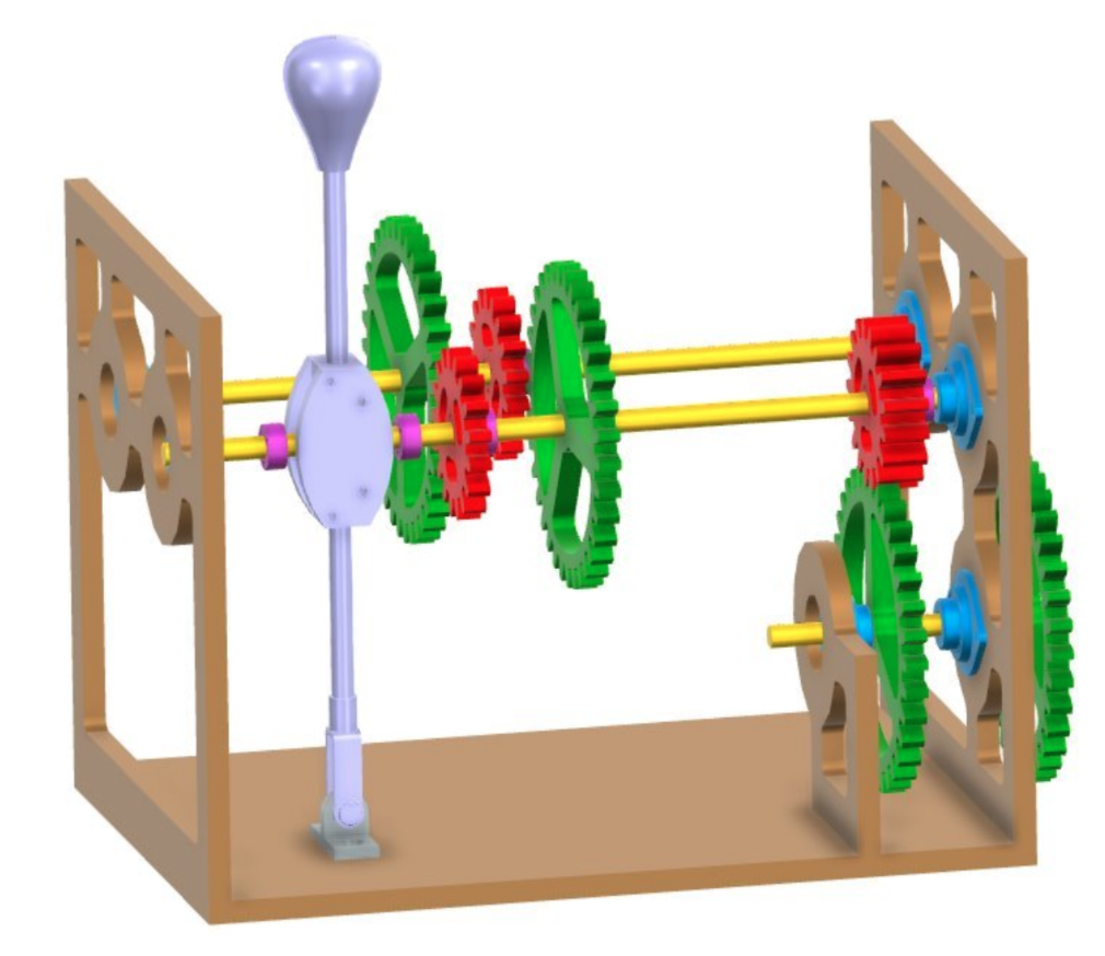
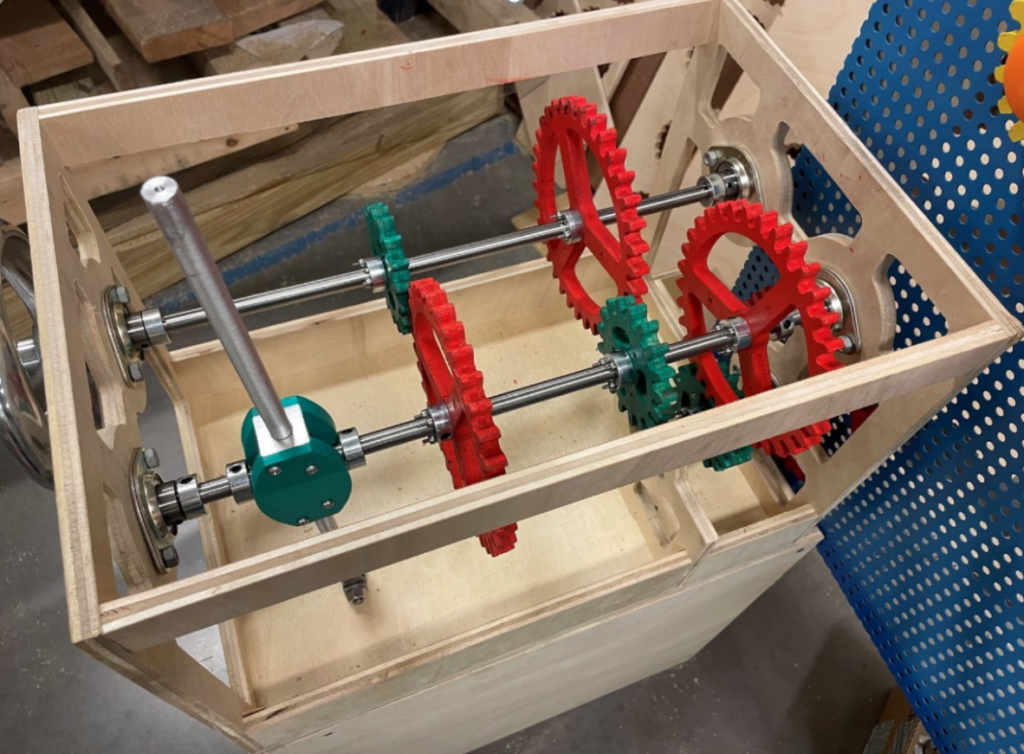
Transmission
The final transmission was significantly upgraded, both in terms of materials and mechanism design. The bearings, shaft collars, and shafts, and hand wheel were all replaced with steel counterparts from McMaster-Carr. The housing and the gears were constructed of 1/2″ baltic birch plywood cut on the CNC Shopbot mill. The shifting handle was redesigned to pivot about a fixed point in the base, rather than be fixed to the shifting axle.
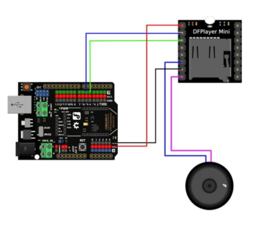
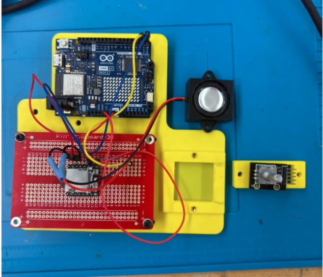
Record Player
The main output component for our third prototype was an audio device that could play a song at different speeds depending on the speed of rotation. A representation of a record player using an arduino audio kit was fabricated and installed in the horizontal surface.
Engineering Analysis
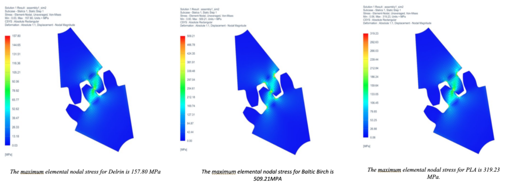
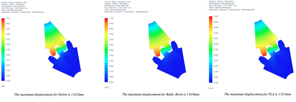
Gear Contact Numerical Analysis
Even though Baltic birch plywood has the largest maximum stress, it does have a similar maximum displacement compared to the other materials. It has a significantly lower cost of $60.98 fora sheet of ½” 4ft x 8 ft compared to a ½” 2ft x 4 ft sheet of Delrin which costs $741.88. Baltic birch is also more environmentally friendly compared to 3D printing using PLA which doesn’t biodegrade well, resulting often in landfills or oceans which is harmful to the environment.
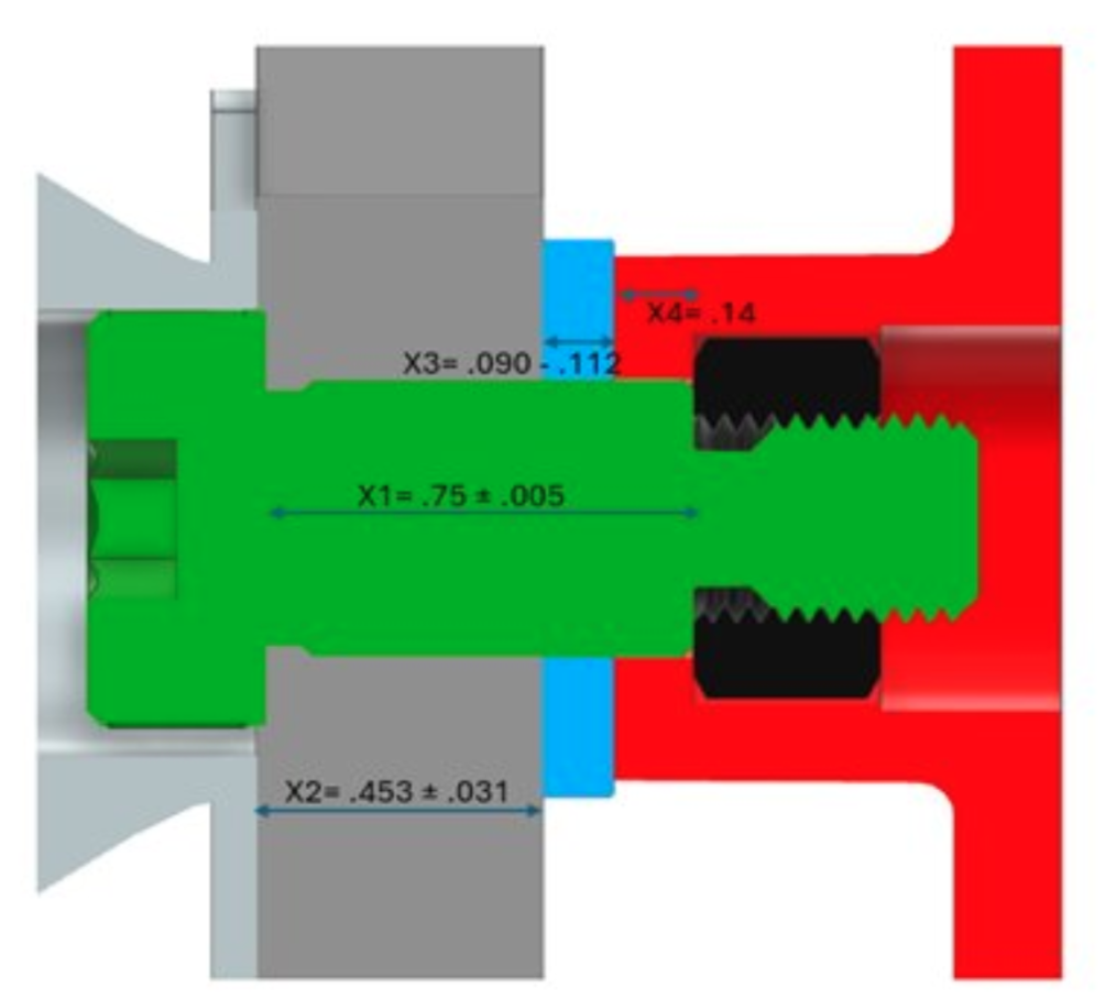
Tolerance Analysis of Play Gear Stack Up
A tolerance analysis was performed on the gear stack up to ensure that the components would not bind in the worst case, and would not have excess slop in the best case. It was found that the minimum gap in the system was 0.009″, and the maximum gap was 0.103″.
Fatigue Analysis of Gears
The repeated meshing of the plywood gears may cause fatigue in the gear teeth. However, due to its heterogeneous structure and the ability to redistribute stress, wood is a material that does not fatigue. A fatigue analysis was performed regardless and can be used as reference in the event that this project is repeated with different materials.
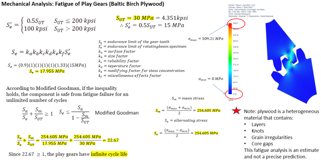
According to the Modified Goodman criterion, the play gears have infinite cycle life.
Conclusions / Future Work
If there was more time to work on the project, a long prototype test would be conducted at the museum. One area of concern with the final prototype was the longevity of the plywood gears. In a longer test, the durability and lifetime would be observed, and a decision on whether the material should be changed would be made. Although the exhibit does a good job of addressing how gears are used to change speed, it does not address how they affect torque. Adding another output that is difficult to move in one configuration, but easy to move in another, might do a better job of addressing the full mechanical advantage of gears.
The interactive gears exhibit will be given to RMSC for future development. The museum will conduct more testing with the third stage prototype, where they will evaluate the durability of the Baltic birch plywood, and whether they would like to switch to a plastic material like Delrin or PLA. Additionally, the museum will test whether the exhibit makes more sense separated into two components entirely, one to teach about transmissions, and one to teach about gears.
All part files and stl files will be given to the museum for production of future components. Once the museum conducts more tests and finalizes the design, they can reproduce components and make changes to the exhibit as they see fit. Ultimately, the exhibit will be incorporated into the How Things Work exhibition, which goes on display at the Rochester Museum and Science Center every summer.
Acknowledgement and Thanks
We would like to extend a special thank you to the following persons for providing their time and expertise to this project. Without them, this project would not have been successful:
Christopher Muir, Chris Pratt, Sam Kreigsman, Bill Mildenberger, Jim Alkins, and Elizabeth Martin
We would also like to thank RMSC, and especially our project supervisor Calvin Uzelmeier and graphic designer Yasmin Jung for granting us this opportunity and providing guidance and support every step of the way.