ME 204- Mechanical Engineering Senior Design
Team Members
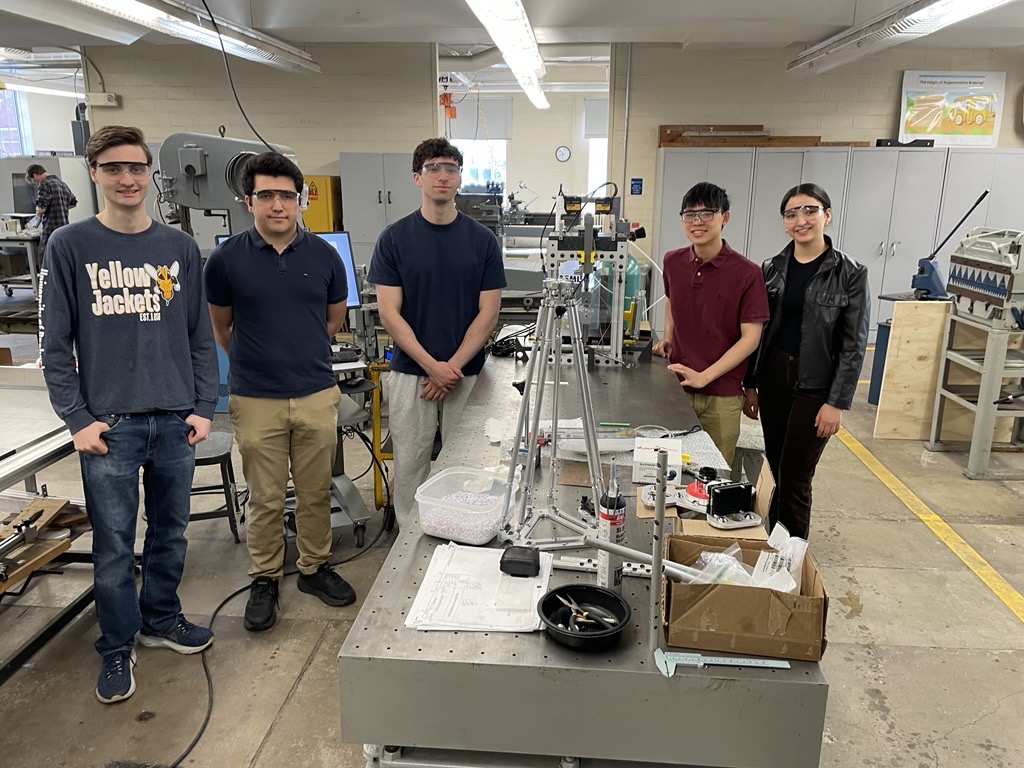
Kaan Aytekin, Michael Bartusek, Darren Chen, Amel Rouabhia, Ryan Zorzi
Problem Overview
Design
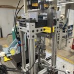
After multiple design concepts and iterations, the team developed a bottom-loading apparatus that applies a downward force below the air bearing’s center of mass. This configuration features a “self-centering” mechanism, which ensures that the applied force remains directly below the bearing and entirely vertical during measurement. The testing rig is integrated into five main subsystems:
- Load Application System: A self-aligning mechanism utilizing tensioned springs to apply vertical forces.
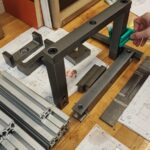
- Displacement Measurement Mount: A bridge-style structure designed to hold high-precision Keyence sensors.
- Support Frame: A rigid assembly holding a precision-ground granite surface plate as the primary datum.
- Air Supply Components: A regulated pneumatic system for delivering and monitoring airflow.
- Safety Features: Structural limits and guards to protect the high-precision components and operators during testing.
Manufacturing & Materials
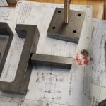
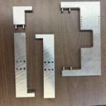
- For the load application subsystem, steel was selected for the loading bars and hex tensioning mechanism to provide high stability and facilitate a reliable preload. This subsystem required 27 hours of milling, turning, and sawing.
- The displacement mount was fabricated from aluminum over 20 hours of mill time, chosen for its light weight and ease of producing the precise tapped holes required for sensor integration.
- To establish a reliable measurement datum, the displacement flag was manufactured from a 0.5-inch steel plate ground to a 2.5-micron flatness, as thinner stock proved susceptible to warping.
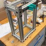
- Finally, the granite support table was constructed using 1.5-inch 80/20 aluminum extrusion, with the ends precision-milled to ensure flat mating surfaces for the granite slab.
Experimental Validation
Experimental validation focused on systematic data acquisition and the elimination of measurement bias through a rigorous calibration protocol. During testing, air was supplied at regulated pressures, and mechanical loads were added incrementally using the hex tensioning tool in roughly 35 lb steps. To maintain data integrity, the system was fully unloaded, and sensors were re-zeroed between every measurement. The resulting data were processed in MATLAB, leveraging the geometric principle that three points define a plane to identify the exact center of the air bearing.
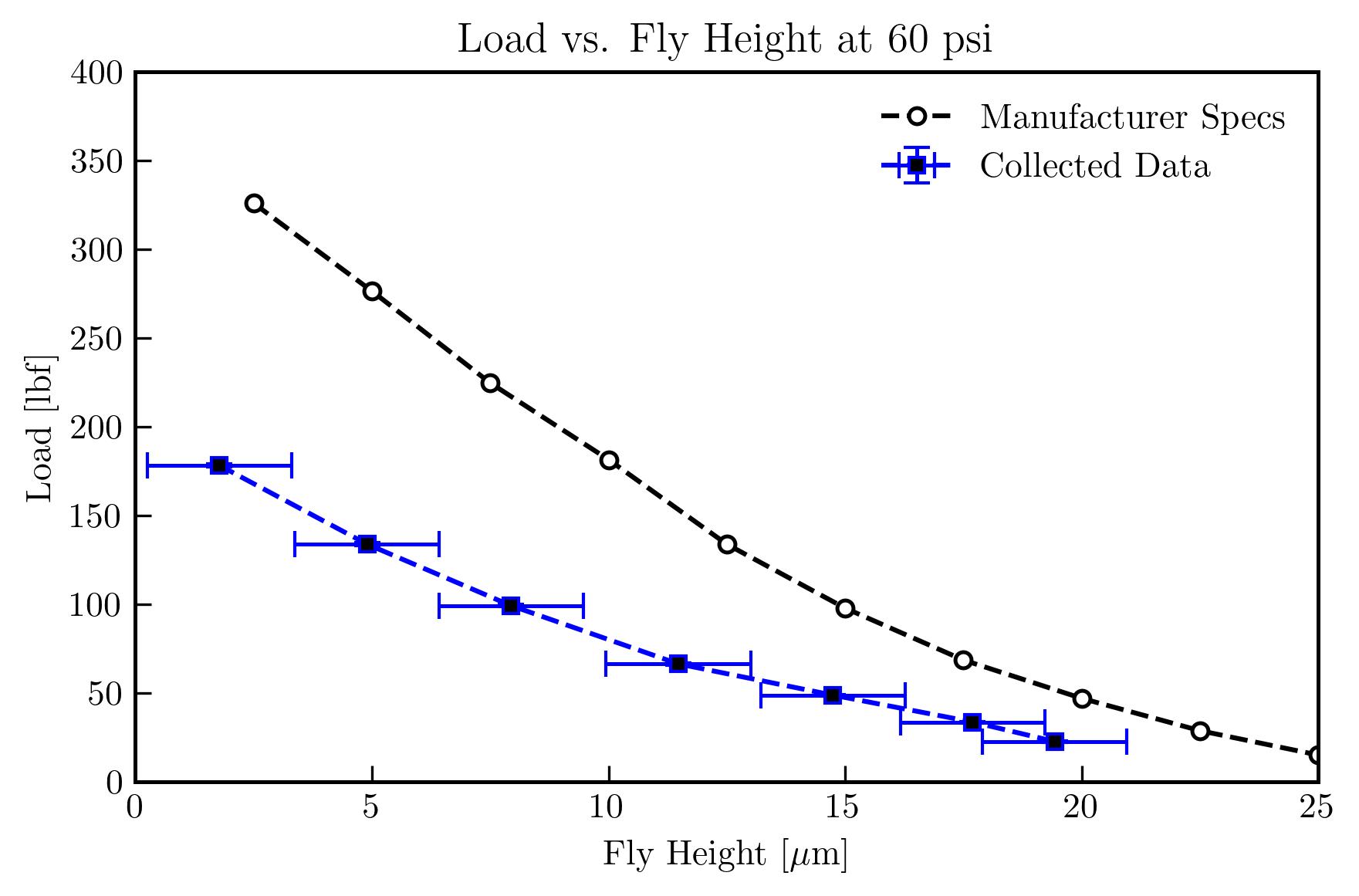
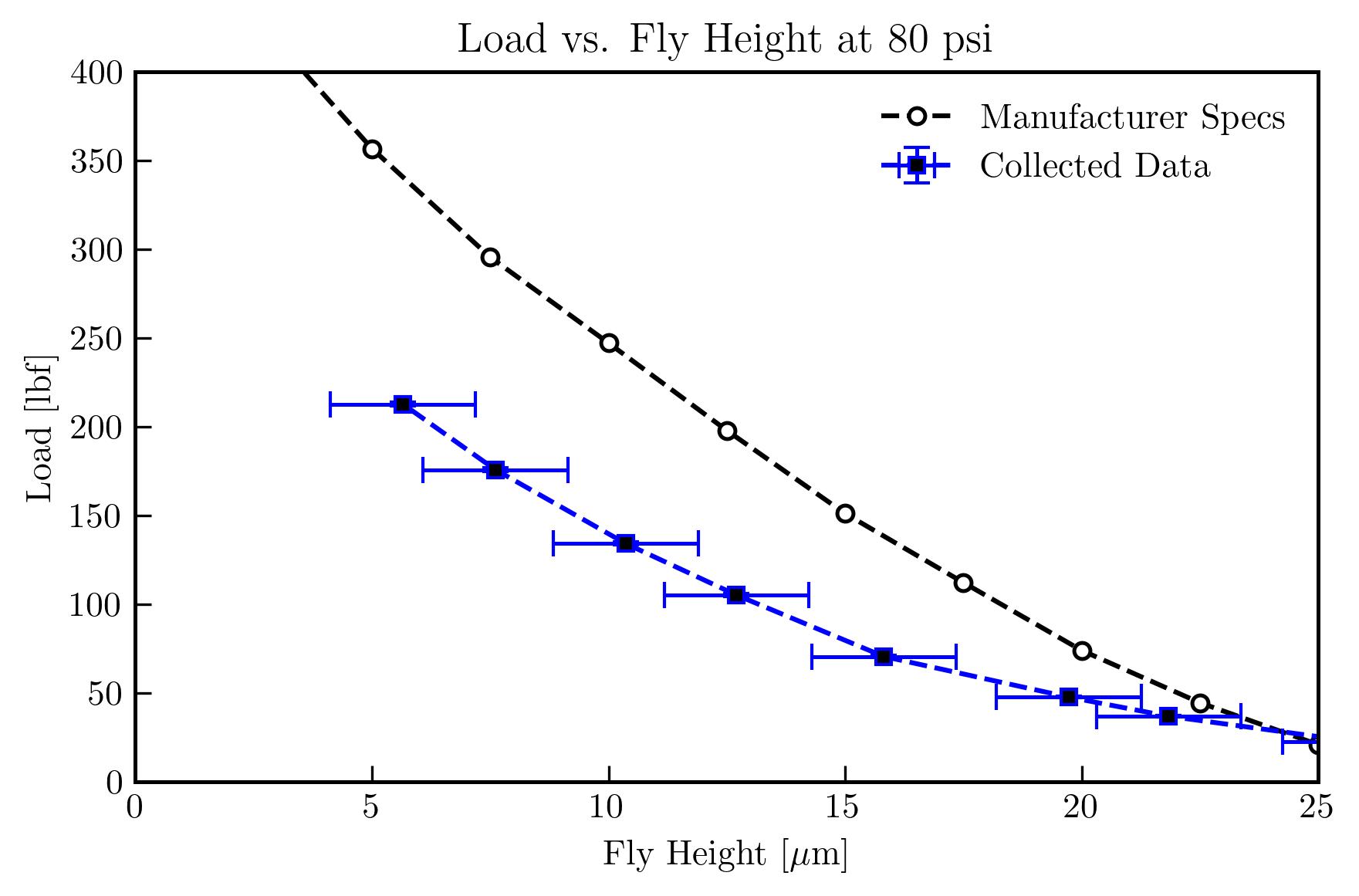
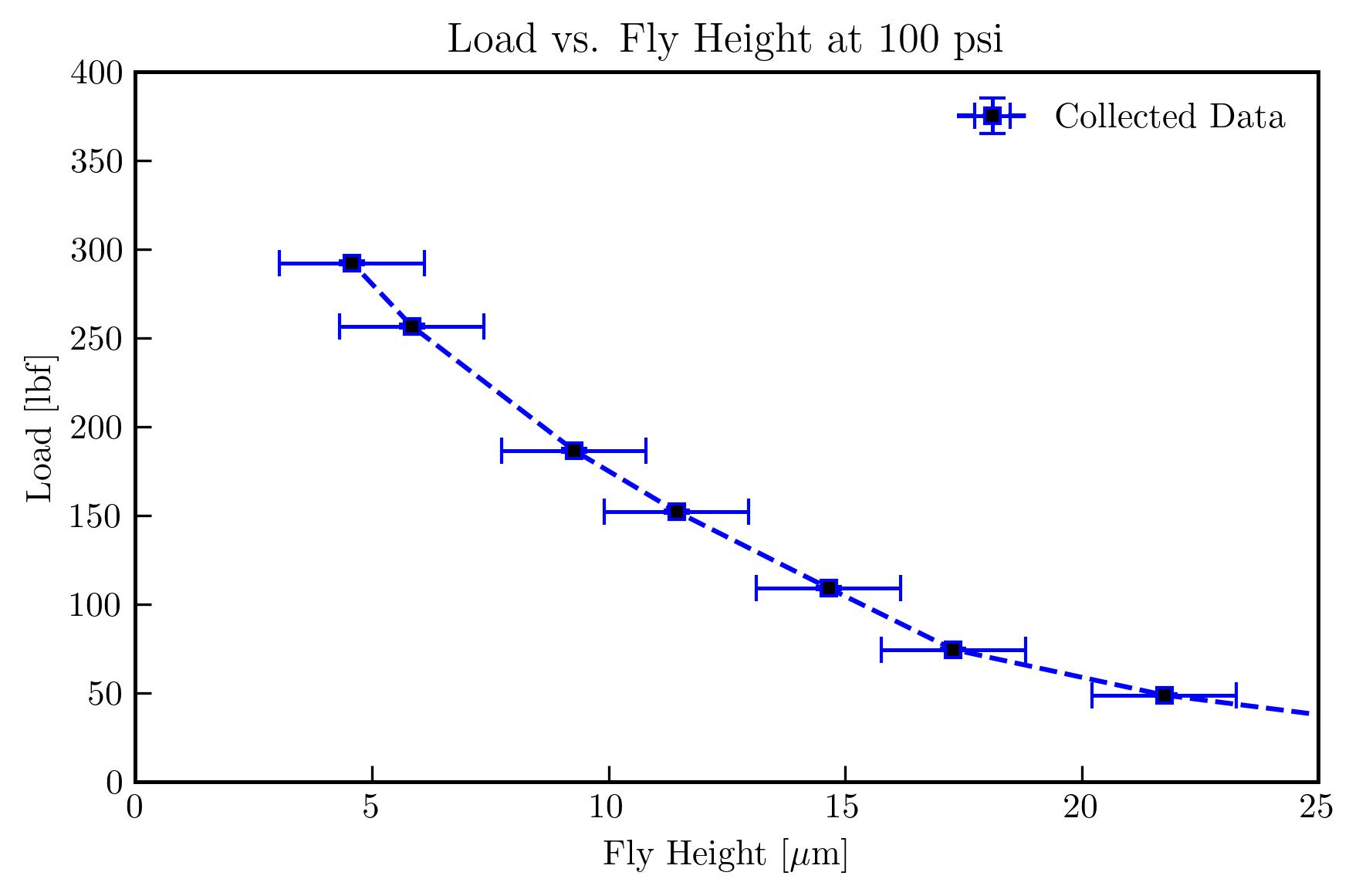
The center fly heights were plotted against the applied loads for 60, 80, and 100 psi of air pressure in the figures below. In terms of fly height measurement, the bottleneck in the uncertainty was the flatness of the flag. The overall flatness of the flag was on the order of 5 microns as measured by a dial gauge on a surface plate. Locally, that is within a ¾ inch radius around where the displacement sensors read, the flatness was around 2 microns. The remainder of the sensor uncertainty was combined with the flag flatness by RSS. For the 60 and 80 psi case, the manufacturer has published load vs. flyheight data, which are plotted along with our results.
Acknowledgments
We would like to thank our sponsor Ognjen Bosic for his guidance on this project, ASML, for accommodating our tour of their facility and sponsoring this project, and the Department of Mechanical Engineering for sponsoring our trip to ASML and funding this project. We would also like to thank Professor Muir for his invaluable technical advice, Christine Pratt for assisting the team with the Keyence sensor operation and air flow consulting, Professor Mohammad for his time assisting with our load cell circuitry, Bill Mildenberger for manufacturing the flag and assisting with machining operations, Sam Kriegsman for an incredible amount of machining advice, Jim Alkins for assistance in the Rettner machine shop, Ed Herger for advising us on displacement measuring techniques, Mason Garlatti and the Chemical Engineering Department for lending us the regulator and assisting with the air supply tubing, Arthur Chen with assistance during setup, and our TA Matthew Hook for helping us in our biweekly meetings.