Mentors
Christopher Muir, Chris Pratt, Mike Pomerantz, Jim Alkins
Project Description
Gas-powered automobiles negatively impact the earth because of pollution that is exhausted from their engines. This project implements a cheap, efficient, and electric-powered cart design to raise awareness on the power of efficient electric vehicles. The cart is divided into four subsystems: drivetrain, brakes, frame, and steering. Each sub-system is designed based on various NX simulations and engineering principles and constrained to a set of requirements and specifications to be as efficient as possible.
Requirements and Specifications
Requirements
The cart must drive with the power of a hand-drill for the entirety of the race
The cart must possess, at a minimum, 3 wheels
The cart must clear the ramp near Meliora without interference
The cart must have safety features (i.e. seatbelt and bell)
The cart must sustain its own weight and the weight of the driver
Specifications
The maximum speed of the cart must not exceed 25 mph
The maximum turn radius of the cart must be 11 ft.
The maximum brake distance of the cart must be 15 ft.
The cart must supports its own weight plus an additional 210 lbs.
The cart must have 6″ of clearance under the frame from the point of maximum deflection to the ground
Concept Selection
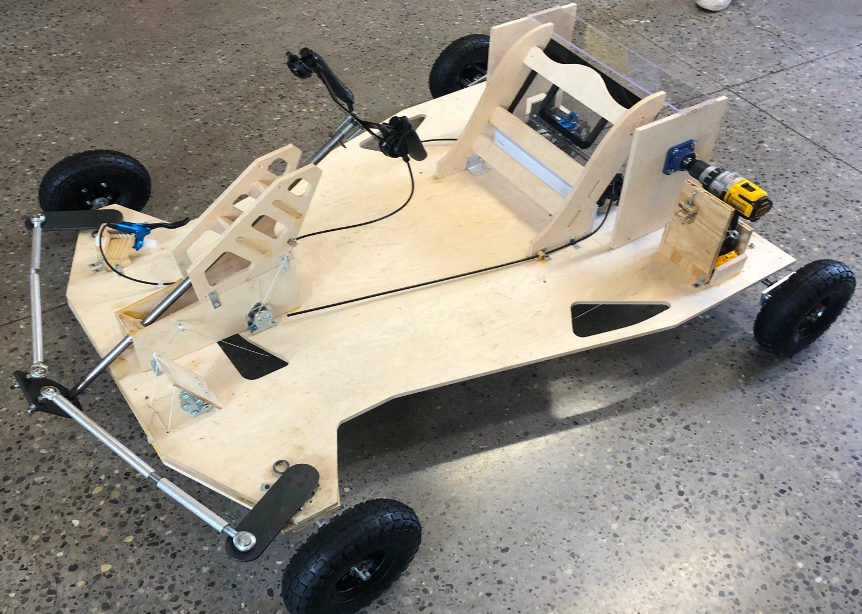
The skeleton of the cart’s frame is made of a base plank of Baltic Birch plywood. It is a single piece of wood for lightweight efficiency. Supports were added under the frame in the front and on top in the back to decrease deflection. The topology of the base frame was optimized, and it has side mounts that extend out for the tires. There is a support at the front of the cart for the steering column and steering wheel, as well as a built-in seat.
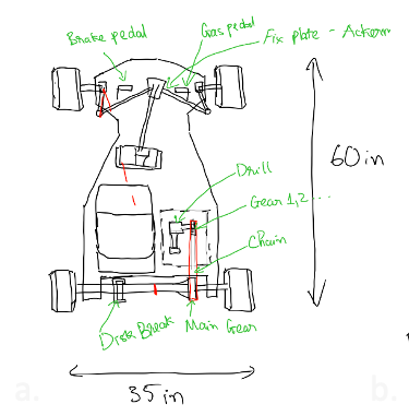
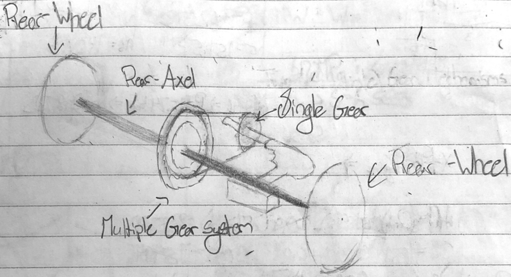
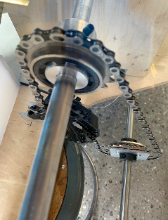
The drivetrain is rear-wheel drive. The main criteria considered for the design are handling, efficiency, ease of manufacturing, size of the drive train, and finally practicality of the design. The drill will be placed in the rear of the car and a sprocket/chain assembly will be used to transfer the power from the drill to the rear axle and ultimately the rear wheels.
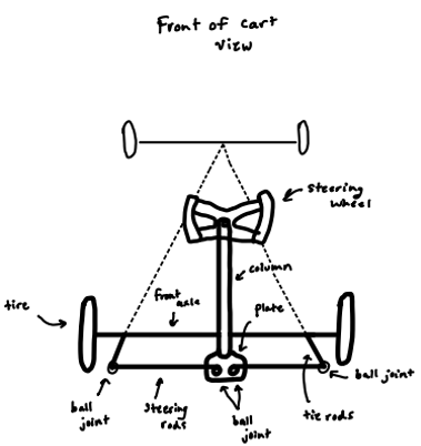
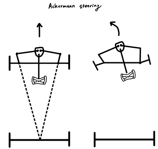
The chosen concept for the steering system uses an Ackermann steering . Ackermann steering reduces wheel slipping. The steering wheel is attached to a steering column, and the column is attached to a plate with two holes on the top. Two steering tie-rods extend outward from the steering plate and attach to the plate with ball joints. The opposite ends of the steering tie-rods are attached to a steering pivot plate, which points towards the center point of the back axle to enforce Ackermann steering.
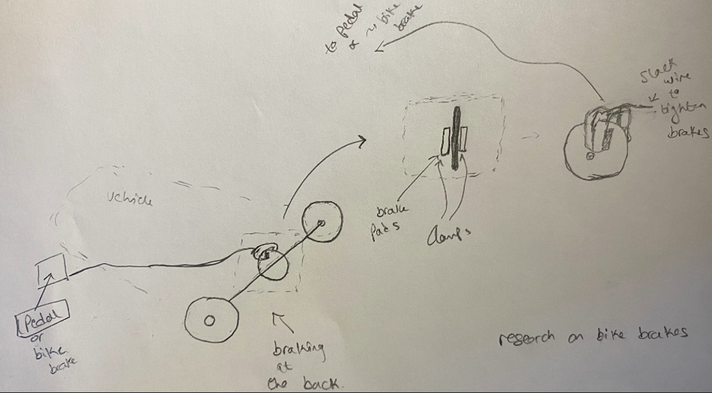
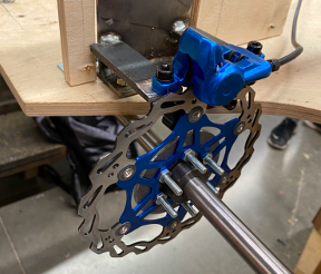
Regarding braking, the selection criteria were complexity of design, manufacturability, thermal efficiency, ease of assembly, and cost efficiency. These most important factors to consider for this sub-system. Hydraulic disc brakes met all the criteria and provided the necessary braking power to meet our requirements.
CAD Drawing Package
Mechanical Analysis
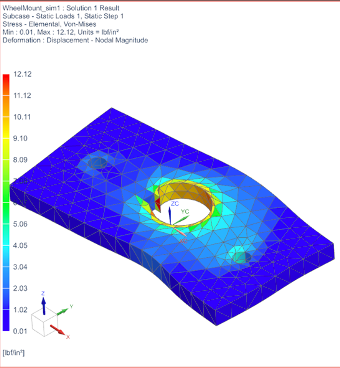
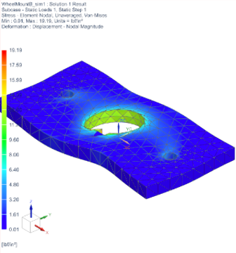
NX Stress Analysis: One of the design considerations was regarding the mounting plates that were used to mount the wheels onto the rear axle. For this part, it was necessary to understand which orientation was best for broaching the central 5/8” hole to fit the key that would lock it in place. The options were to key it vertically or horizontally; the team wanted to see which orientation would result in the least amount of stress transmitted to the plate. A 1 lbf/in torque was placed in the center and two other holes were fixed before running a Solution 101 Statics analysis on the plate to see the resultant stresses. The results showed a maximum stress of 12.12 psi for the vertical orientation while the horizontal one showed a maximum stress of 19.19 psi. Although the vertical orientation had less stress, we realized that the orientation would not matter since the yield stress of aluminum is 40,000 psi and therefore the stresses in either orientation would be negligible.
Dynamics Analysis: The purpose of this design project was to convert the torque from on hand drill to torque that will drive the cart and its passenger forward. For this, a dynamic analysis was done on the cart. The baseline equation for the analysis is,

where Tapplied is the torque applied to the rear axle, Wcart is the weight of the cart, s is the coefficient of static friction between the tires and the road, “r” is the radius of the rear tires, I is the moment of inertia of the tires and the rear axle, and α is the angular acceleration. This equation was used to find the necessary torque necessary to achieve an agreed upon acceleration. The equation had a numerical answer; however, after testing the drills, it was determined that this number was not valid because the torque output of the drill changed as the speed of the drill increased.
Manufacturing
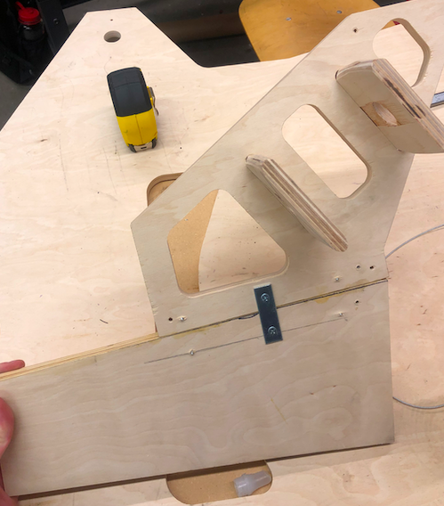
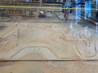
Frame: The frame consists of three parts: base frame, steering column support, and driver seat. All these components were manufactured using 1/2” Baltic birch plywood in the ShopBot CNC machine. This machine is quicker than using a traditional bandsaw, and it allows for irregular shapes/curvatures to be cut. A spot drill and a 1/2” drill (with a 16000-rpm spindle speed and 100 ipm feed rate) were used. The band saw was used for touch-ups and small pieces.
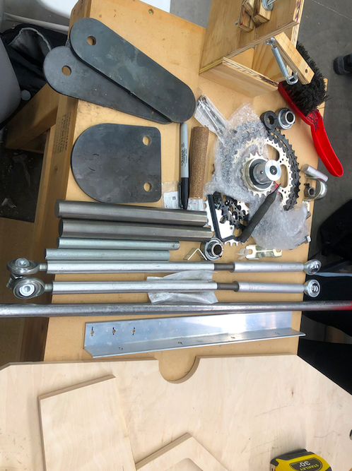
Drivetrain: For the drivetrain, the keyed shaft used for the rear axle is made from 1045 Carbon Steel because of its strength and manufacturability. The mounting plate for the sprockets and for the tires were machined from aluminum using the mill. The aluminum connecting rods to the tires from the mounting plates were machined on the lathe and threaded.
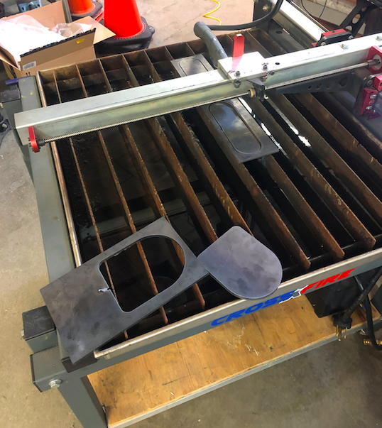
Steering: For the steering system, all components were made from various steels because of its strength and durability. The steering plate and two pivots were made using the plasma cutter. All three pieces are 1/4” thick, and they were cut using a 0.05” drill at 70 ipm. Holes were drilled in the pieces using the drill press. The steering rod was MIG welded to the steering plate, and the two rods were welded in the pivot sub-assemblies.
Brakes: The hydraulic braking system was attached using various fabricated mounts. The mill and band saw were utilized to manufacture the mount disc and the caliper mount. Welding was also used for the caliper mount.
Testing
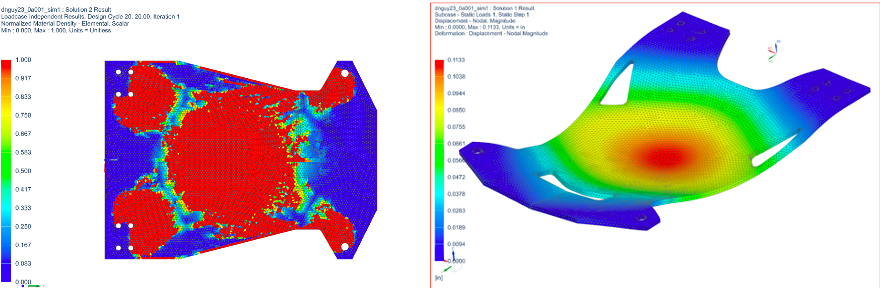
The maximum speed specification, which states that the cart must not exceed 25 mph, was tested using a speedometer. The maximum turning radius of the cart must be 11 ft, and this was tested by coating the front wheels in water and turning the steering wheel as far it can go and driving the cart in a circle (left or right). The radius of the circle was measured with a tape-measure. The maximum break distance of approximately 15 ft was measured by full-stopping the cart from its maximum speed. Marks were made both at the maximum speed and at the final position, and a tape measure was used to measure the distance between the marks. The strength of the frame, which must hold its own weight plus an additional weight of 210 lbs., was measured using an FEA of the frame. Lastly, the clearance under the cart, which must be greater than 6”, was measured using a tape-measure from the ground to the point of maximum deflection in the frame while the driver is in position.
Results
| Specification Test | Results (PASS/FAIL) |
| Maximum speed < 25 mph | PASS |
| Turn radius < 11 ft | PASS |
| Maximum brake distance < 15 ft. | PASS |
| Must support weight of driver | PASS |
| Clearance > 0.5 ft. | PASS |
Recommendations For Future Work
If given the opportunity of time, a more in-depth NX simulation would be recommended. A simulation of each sub-system (brakes, steering etc.) as well as a full cart in motion simulation where the forces and stresses are examined would be recommended. Another recommendation is to include potential political turmoil as part of your CPM’s unexpected events that may disrupt the supply chain of certain products and parts that are used in the manufacturing of the cart. Furthermore, a more advanced gearbox and lighter, more aerodynamic frame will also improve cart performance.
Acknowledgements
Our team would like to acknowledge Professor Muir for his constant support and help throughout the semester. A special thank you is also extended to Mike Pomerantz, Chris Pratt, and Jim Alkins for their insight and guidance.