
Abstract
Hypersonic flow (a classification given to flows above Mach five) is studied to better understand the flight conditions for experimental aircraft, re-entry vehicles, advanced missiles, and minor astronomical bodies. The use of pulsed lasers in hypersonic flow environments is an emerging field of research that is applicable to defense, high speed travel, and astronomy. This project aims to design, build, and test a data collection system for a group at the Laboratory for Laser Energetics (LLE) that can characterize a shock wave produced by a pulsed laser acting on a body in hypersonic flow. Pulsed lasers operate on the nanosecond timescale (6 ns pulse length), and most hypersonic wind facilities can deliver steady state flow on the millisecond timescale (<100 ms), which creates the need for high sampling rate data acquisition and carefully calibrated mechanical systems. The Hyper group investigated the use of a custom-built fiberoptic interferometer, rosette strain gauges, and schlieren imaging for collecting data from a test subject in hypersonic flow. Through the testing of two distinct prototypes, the group was able to develop a better understanding of both hypersonic flow and pulsed laser effects while also working towards a better characterization of the capabilities of strain gauges in measuring these extreme conditions. The use of strain gauges, fiber-interferometry, and schlieren imaging could be used in a third iteration sting that accurately collects data from pulsed lasers in hypersonic flow. This data could be implemented in the defense industry, high speed transportation, and other hypersonic applications
Problem Definition
Laboratory for Laser Energetics (LLE) is studying the interactions of lasers with objects in hypersonic flow. Currently, the lab does not have a method of directly measuring laser-applied forces in a hypersonic environment. Commercially available load cells do not have the combined sample rate, resolution, and robustness required to measure such a short, intense deposition of energy in the extreme conditions seen during hypersonic flight. This project aimed to deliver a prototype measurement device capable of collecting data on the shock produced by a pulsed laser in a hypersonic wind tunnel. Such a device would enable the correlation of analytical predictions and observed flow disturbances with the force applied to a test subject. Additionally, this project aimed to develop a better understanding of different measurement techniques and their applicability to pulsed laser effects in hypersonic flow. Due to the widespread use and availability of strain gauges, a better understanding of their ability to resolve pulsed laser shock was desired. Finally, the group sought to experiment with creating a fiber interferometer as its resolution and sampling rate is very high. Crucially, this project aimed to advance knowledge in the field of laser-plasma interaction and aid national security efforts led by the United States.
Team Members





Deliverables, Requirements, and Specifications
The main deliverable for this project was a prototype device designed to measure forces applied by a laser in at least one degree of freedom. In addition to the prototype, the team was tasked with providing simulation data, analysis data, and other supporting documentation for the prototype. Included in the documentation was a technical report outlining the design of the system and progression between iterations. The provided documentation, prototype, impulse hammer, and measurement system would allow for recreation of the device and a clear path forward for future work and redesign.
Requirements
| Requirements | |
| 1 | Must not experience mechanical failure when subjected to hypersonic flow |
| 2 | Must be compatible with diagnostics known to the PLE group |
| 3 | Must be able to resolve impulse load applied via pulsed laser |
Specifications
| # | Value | Specification |
| 1 | 10 FoS | Minimum factor of safety for mount |
| 2 | 1 DoF | Minimum number of data collection axes |
| 3 | 300 kS/s | Minimum sampling rate |
| 4 | 0.2 lbf | Minimum resolved load from impulse hammer |
| 5 | 500 lbf | Minimum acceptable flow load |
| 6 | 1 ft3 | Maximum design envelope |
| 7 | 48 in. | Maximum flow diameter |
| 8 | 1 kHz | Minimum natural frequency |
Concept Selection
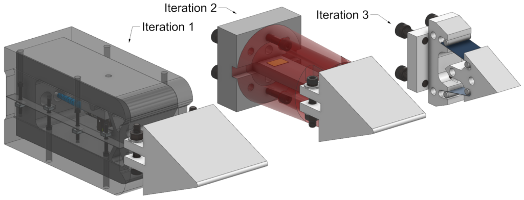
The concept selection process evolved through several iterations as the team learned more about the wind-tunnel environment, sensing constraints, and the laser-loading response of the sting. At first, the design used sensors and imaging methods that were difficult to integrate directly into the hypersonic flow path, so the team moved toward a more protected and controllable measurement approach. That ultimately led to a first-iteration concept centered on a compliant mechanism, a custom fiber-optic interferometer, strain gauges, and high-speed imaging, all aimed at measuring very small deflections as reliably as possible.
A major reason for choosing that direction was sensor practicality. The team found that a commercial displacement sensor was not vacuum rated, and a laser beam placed directly in the flow would likely lose accuracy, so they needed a system that could live inside the sting while staying protected from the tunnel environment. After reviewing commercially available interferometry options and finding that the lead times were too long, the group decided to build a custom interferometric system instead. That gave them a setup tailored to the experiment.
For the first iteration, the compliant mechanism was iteratively designed and analyzed in NX with NASTRAN to ensure the system would rotate predictably at the web junction, giving measurable strain and mirror tilt. The group also used a “Frankenstein” prototype to verify that the basic concept could transfer motion away from the wedge into a location that was easier to measure. When the full-scale device was tested, however, it turned out to be too stiff to produce measurable displacement under the laser loading. That result showed that the initial concept was sound in principle, but not flexible enough in practice for the actual loading conditions.
From there, the team pivoted to a simpler cantilever beam and wedge design, which reduced complexity and better matched the time and fabrication constraints of the project. The new concept still relied on FEA-driven sizing, but it shifted the goal toward achieving measurable displacement with a more straightforward structure made from 1018 steel for easy welding and assembly. When that design also proved too stiff, the group shifted again toward a beam-and-strain-gauge test approach to better understand the character of the laser loading itself.
Development & Analysis
For each iteration, the design process required significant analysis work to determine part geometry, commodity parts to order, and potential failure modes.
Simulation
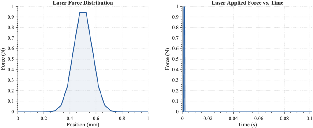
Upon selecting the compliant mechanism concept, the next task was to determine the exact geometry and material that will exhibit the desired behavior. Based on the predicted sensitivity of the interferometry system, the team targeted a mirror tilt of 0.1 degrees when loaded by 1000 lbf for 1 millisecond. The exact spatial and temporal distribution for the load case can be seen below. The primary independent variable which was used to adjust maximum stress and mirror tilt was the thickness of the webbing in the compliant mechanism.
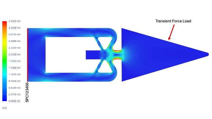
The FEM model can be seen above. A 2” thick paver CQUAD4 mesh was applied to a two-dimensional profile of the compliant mechanism with an element size of 0.05” within the main body and a reduced element size of 0.0025” at points of interest. A convergence study was done on this refinement sizing. This meshing strategy was selected to reduce the computational power spent on regions that experience little stress and increase the fidelity in regions that have stress concentrations, such as the joint of the webbing and the diving board. The model has a fixed constraint along the rear face and uses the load case described above. SOL129 with a time step of 1 microsecond was used to study the nonlinear transient response of the body. In deciding what material to make the mechanism from, the maximum stress was the first thing considered. The FEA found that there is a max stress of 44.25 ksi at the fillet connecting the compliant mechanism to the wedge connector, as seen above. This value exceeds the yield stress for 6061 Aluminum, so 1018 HR Steel was considered next. 1018 HR Steel has a yield strength of 50 ksi, which results in a Factor of Safety of 1.13. Since steel is significantly stiffer than aluminum, we used the FEA results to ensure that the mirror tilt was still in the acceptable range. As this meets the material demands, is easily procurable, and can be easily manufactured, the team selected 1018 steel for the main body of the device.
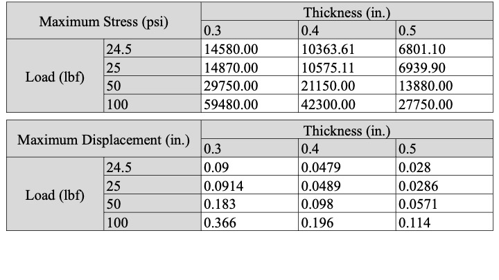
After the team pivoted to a cantilever-based mechanism, another FEA study was conducted to determine dimensions for a steel beam that will exhibit the desired response. The primary independent variable for this study was beam thickness. Simulations were done across a range of scale factors applied to the same load distributions. The scale factors tested were 24.5, 25, 50, and 100. The results of this study can be seen in the table above, and the team used this information to select a 0.3” thick 1018 steel beam.
Interferometry
The custom interferometric system employed fiber-optic cables to improve flexibility and ease of use during testing, Figure 14. A helium-neon (HeNe) laser emitting red light at 630 nm was directed into a collimator. To achieve the precise alignment required, the laser was mounted on a tip-tilt stage, while the collimator was positioned on a three-axis translation stage, seen in Figure 15. This combination provided five degrees of freedom, which was necessary because of the extremely small core diameter of the fiber-optic cables. Slight misalignment would prevent the laser light from coupling effectively into the fiber.
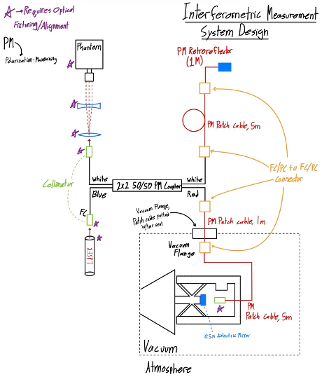
Before entering the optical system, the laser beam was polarized. Polarization refers to the orientation of the electric field oscillations in the light wave. In polarized light, these oscillations are confined to a single plane, which is essential for interferometry because it ensures consistent wave behavior and maximizes interference contrast. The polarized beam then entered a fiber-optic coupler, which split the incoming light evenly into two paths. One beam was directed toward a stationary reference mirror, while the other was sent to the test specimen, as seen in Figure 15. After reflecting from their respective surfaces, both beams reentered their fibers and returned to the coupler, where they recombined. The resulting interference pattern, which contains information about any displacement of the test surface, was then routed through a fourth fiber. Finally, this output light was projected onto a Phantom high-speed camera for recording and analysis.
Fatigue
A fatigue analysis on the worst-case load scenario on the top bolts yielded the result that under the Modified Goodman Criterion predicts a finite life. This was found by using ultimate strength (Sult), σa, σm, and Se. The modification factors for the bolt were found to be Ka=0.6923, Kb=1, Kc=0.85, Kd=1, Ke=0.8139, and Kf=0.33. With a Sult value of 170 ksi Se was to be 13.43 ksi using the following equation.
Using the maximum tension felt in a bolt Fmax of 4815 lbf of tension and the minimum tension Fmin of 3315 lbf of preload and the following equations, the stress amplitudes σa and σm were found to be 14.31 ksi and 45.94 ksi, respectively.
Where At is the Tensile Stress Area. Then the values of σa, σm, Se, and Sult were inserted into the Modified Goodman Criterion of:
The left side of the equation yields a value of 1.34. As this value is greater than 1, the Modified Goodman Criterion predicts a finite life.
Testing & Results
A crucial part of this project is testing and validation of the system being developed. Before any hypersonic testing could be performed, researchers had to first demonstrate that shock delivered by a pulsed laser could be resolved and analyzed in a laboratory setting.
The first requirement, no mechanical failure due to hypersonic flow, was validated using NX. Simulations suggest that the prototype would not fail, but without hypersonic testing this requirement cannot be verified. The second requirement, compatibility with diagnostics currently used by the LLE, was met for both iterations. The third requirement, resolution of a pulsed laser impulse, was tested at the LLE using a focused laser that could deliver 2.2 Joules of energy to the sting. This requirement was added because the team found that this task was more difficult than expected. This requirement was not met in either case. The figure below shows a laser shot test on the iteration 1 design. As can be seen, there is no obvious response.
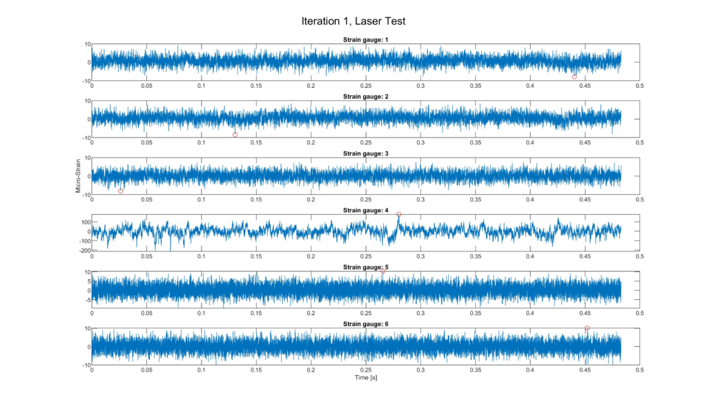
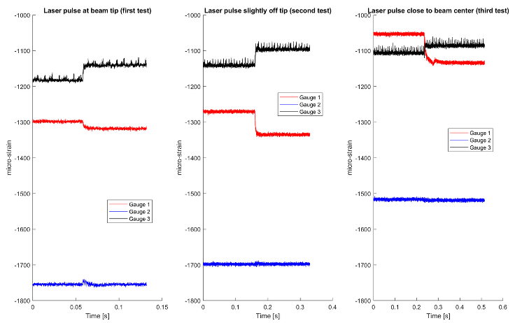
Requirement three represents the area with the most room for improvement. Multiple laser shots were performed on both versions of the prototype, and neither were able to resolve any meaningful data, as shown above. In an effort to better understand the load applied by the laser, the team tried shooting a simple cantilever beam and were able to see an electrical response, but the testing did not yield expected results. As shown below, the strain gauges provided an electrical response in the form of a jump in voltage, recorded as a jump in strain. It is unclear the exact meaning of this jump, but in any case, the pulsed laser shot results in a change in resistance in the gauge. Future work would include replication of this testing to better understand the capabilities of strain gauges for impulse laser data collection.
Recommendations for Future Work
Given extra time, the group would go through another design cycle using the new understanding of loading conditions, shock behavior, and the capabilities of strain gauges. A potential concept design using thin spring steel webs to further increase displacement is shown below. There are concerns, however, that a highly compliant system would be prone to extreme deformation or buckling when subjected to hypersonic flow. Furthermore, the coupling of diagnostic systems that require very small deformations (interferometry, strain sensing) with systems that require large deformations (Schlieren imaging) will hinder all the measurement systems’ ability to record the desired behaviors. This calls for designing either a system that utilizes diagnostics that measure entirely using large deformations (millimeter-scale), or entirely small deformations (micrometer-scale).
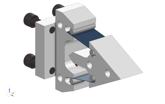
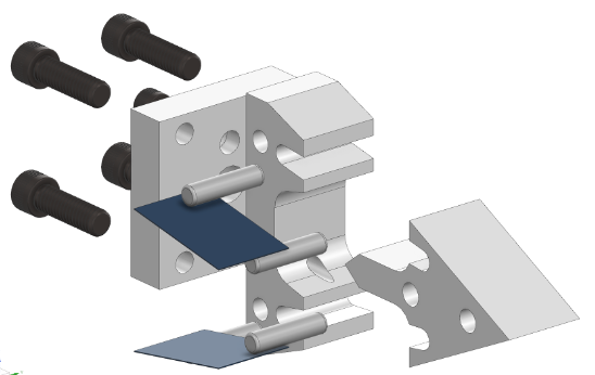
Despite the technical delays that prevented the group from using the fiber-optic interferometer for diagnostics, the system appeared to have promising performance characteristics. After discussing the operation of the actual wind tunnel with engineers at CUBRC, there are serious concerns such as high vibration and movement of the tunnel during testing which cannot be ignored when considering the effectiveness of the interferometer.
As far as diagnostics that this project did not cover, photon doppler velocimetry (PDV) appears to be very well-suited for indirectly measuring the impulse delivered by a pulsed laser. PDV systems can measure the high-speed movements of materials when they are subjected to shock, vibration, or other dynamic loading. In this case, the intensity of the shock generated by a pulsed laser could be correlated with the impulse required to create the shock. It is possible, though, that employing the PDV system to measure force would also be subject to the same limitations of a Michelson interferometer like the one the Hyper group developed as it is also an optical measurement technique.
Acknowledgements
The Hyper group would like to thank:
- Christopher Muir
- Edward Herger
- Kyle Christensen
- Valerie Fleischauer
- Benjamin Martin
- Vincent Tagliamonti
- Jerry Chung
- Riley Flaum
- Chris Pratt
- Jim Alkins
- Bill Mildenberger
- Samantha Kriegsman
- Elizabeth Martin
- Hottinger Brüel & Kjær