Project Overview
Our project involves the the creation, from preliminary optical design to final physical systems, of three beam expander prototypes using 3-D printed mechanical housings. The designs have varying lens counts of 2-, 3-, and 4-lens systems. We have used Edmund catalog lenses in Zemax to design the 3 beam expanders, each with 5x magnification. Following the creation of these optical designs, we have used CAD software to create a set of mechanical housings to go with them. Once the physical prototypes are finalized, they will be tested for wavefront error and beam deviation. These values will then be compared to the theoretical performance of the lens design files back in Zemax.
Team Members
Andrea Denman: Project Coordinator
Jack Maness: Optical Designer
April Wang: Mechanical Designer
Customer
Nick Smith – Edmund Optics
Student Advisor
Erick Begishev – Mechanical Engineering Major
Vision
Optical software is essential in the prototyping process especially with the ability to use software to import catalog lenses into designs. However, beyond this little has been done to integrate the mechanical aspect of design to create a finished prototype. Edmund sees 3D printing as a potential solution to this shortcoming. Their ultimate goal beyond our project is to implement an automated software that outputs a mechanical model to be 3-D printed alongside an Edmund Optics optical design solution.
The goal of our project is to create three designs, 2-, 3- and 4- element designs each with 3d printed housing to compare performance in software versus physical products. Throughout our design and production, we have been asked to document our process and be sure to acknowledge the difficult aspects of the process. All lens elements that will be used during the designing and manufacturing processes will come from the Edmund Optics catalog. This will allow Edmund Optics to have their own lenses as reference for feasibility. However, the mechanical housing, its design and materials, will come from our group and the University of Rochester. While previous iterations of this project included comparison of a 3D printed design with a machined aluminum design, this will only focus on the prototyping capabilities of 3D printing. More finalized lens housings (i.e. a housing made of aluminum) will not be pursued.
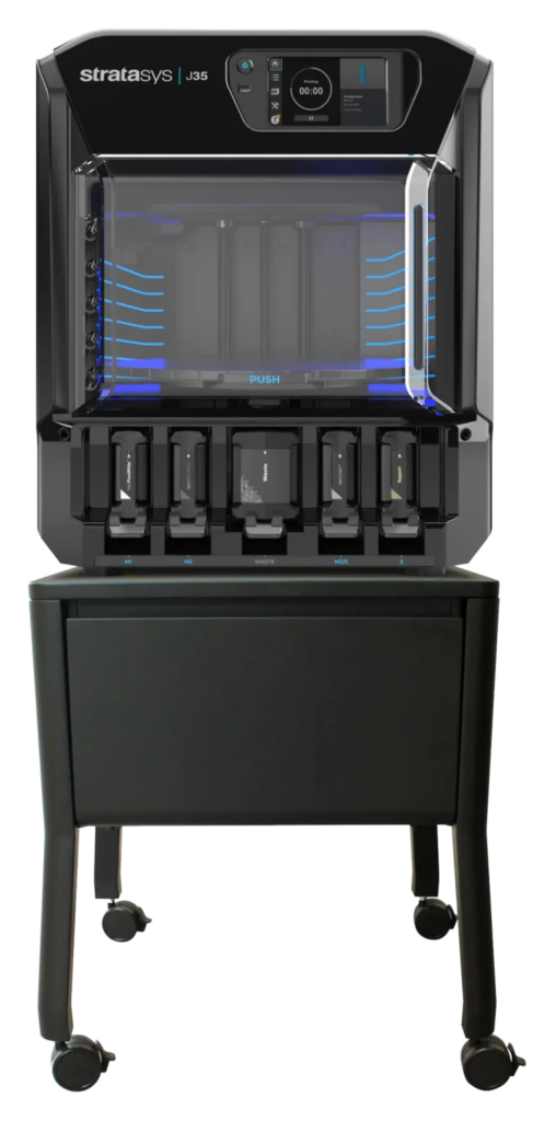
Printer Choice
- Stratasys J35 Pro 3D Printer
- Resolution of ~150um
- Lower cost than other options
- Quick printing time (all 3 housings printed in one day)
Optical Design Process
The specifications of these systems in software were open-ended and were primarily important for comparison to the final design after 3-D printing. Some requirements were made for the designs themselves including:
- Magnification: 5x (Afocal)
- Incoming Beam Diameter: 3mm (outgoing beam of 15mm consistent with 5x magnification
- Edmund catalog lenses
- Lens diameters at least 3x larger than the beam diameter at the lens (used to limit aberrations from the curvature of the lenses)
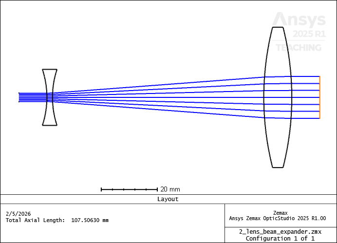
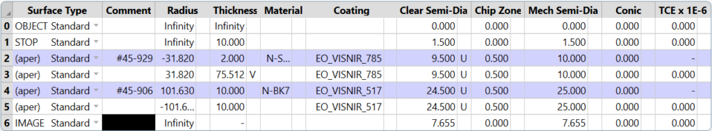
2-Lens System
In designing the 2-lens system, we were able to use first order geometrical optics to find a combination of lenses that worked for creating an afocal system. Once lenses were chosen, the next challenge was spacing them correctly to have close to 5x magnification and parallel rays on either side of the system. For optimization, we used the feature “Quick Adjust” in Zemax with afocal mode turned on. This allowed for rapid adjustment of the spacing between the lenses to create the entrance and exit beams we wanted.
One limitation in using catalog lenses is that the specifications are unlikely to be achieved at high levels of precision. For example, this system had a magnification of 4.77x. Not quite the specification of 5x, but still considered acceptable by our customer due to the limits of catalog lenses.
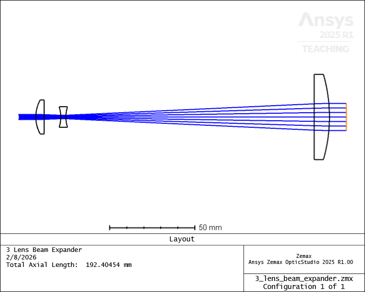
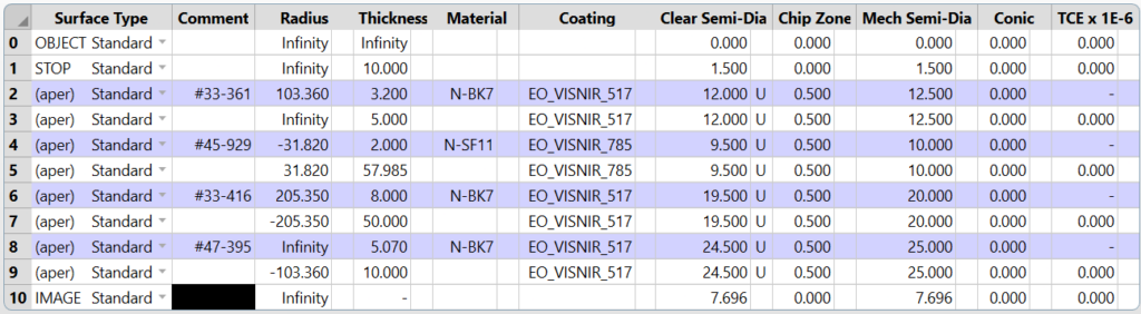
3-Lens System
For the 3-lens system a similar method was used. Initial designing was done using first order geometrical optics. However, with 3 lenses the margin for error increased and some minor changes to individual lens choices were made. For example, an adjustment for the final lens in the system seen below was choosing between an effective focal length (EFL) of 175mm or 200mm which, while small, made a difference in how accurate we were to our goal magnification of 5x. With the set up shown below a magnification of 5.04x was achieved.
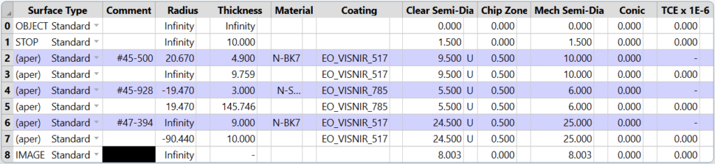
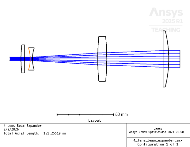
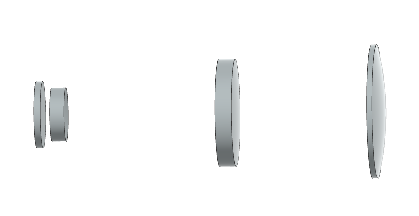
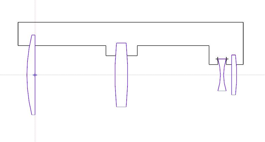
4-Lens System
For the 4-lens system again first order geometrical optics were used to determine rough estimates of what the system should look like. With more lenses though, more room for small adjustments in the system. This resulted in some trial and error with the lens choices to help with the final specifications. A magnification of 4.93x was achieved.
Mechanical Design Process
Using the previous year’s group’s “poker chip”, we drew the housings in Siemens NX for all 3 systems.
The lens designs were downloaded as .STEP files from Zemax, so they could be opened as a 3D model in NX.
Then, we drew planes around the lenses and used intersection curves to create 2D drawings of the lenses, so we could copy them into a new project to trace the housing around them.
Once the shell was done, we toleranced the casing. The printer’s resolutions limit was 0.1778mm, so we tested out a few different tolerances, from 0.2 to 1mm. 1mm was found to be too much, as the lenses would fit loosely in the casing. 0.5mm was found to be the most suitable tolerancing.
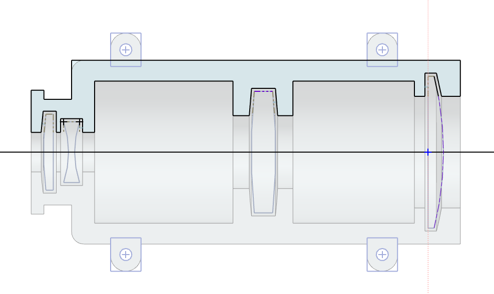
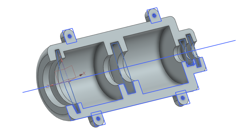
Then, we do a 180 degree revolve to create half of the system. This process only works with radially symmetric objects, so it would not be suitable for freeform optics.
Additionally, the mechanism to clamp the two halves together is square extrusions with holes to fit helical inserts and screws.
We chose M3 Helical inserts with a drill size of 3.2mm, so we set the holes of the female side to be 3.15mm so we could drill the helicoils into them. The holes on the male side were 4mm so they could easily fit the screws.
Testing Method/Results
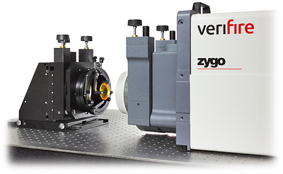
To test our beam expanders we have used the Zygo Verifire (pictured below) for Wavefront Error measurements. The system uses double pass interferometry by sending a 633nm collimated beam through the system to reflect off of a flat mirror to be passed back through the system. Once passed through the Verifire will analyze the interference fringes and return values for peak-to-valley (PV) wavefront error and root mean square (RMS) wavefront error.
Our tests had 3 trials per system and unfortunately, due to an unforseen delay measurements for the 3-lens system have not been conducted at this time. The following chart displays our comparison of theoretical perfromance values in Zemax with the measured values in the Verifire:
| Wavefront Error – Zemax (Waves) | Wavefront Error – Measured (Waves) | |
| 2-Lens System | PV – 1.7142, RMS – 0.5166 | PV – 0.930, RMS – 0.148 |
| 3-Lens System | PV – 0.8802, RMS – 0.2533 | Unable to measure at this time |
| 4-Lens system | PV – 0.8508, RMS – 0.2458 | PV – 1.754, RMS – 0.314 |
Conclusion
Throughout the testing process, the performance got worse with additional lens count, likely due to greater opportunities for error in systems with more lenses. The tolerancing was also difficult to pinpoint, as there would be variances in each print as well. We would err on the larger side, to ensure the housing doesn’t exert pressure on the lenses. Much more trials on 3D printing + testing would need to be done for Edmund to implement an automated software to prototype the correct tolerance. It is worth noting that systems were all approximately 200mm in length and and 70mm in diameter. Each print uses up a lot of print material and is considered a massive job, taking 5-18 hours at a time. The monetary and time cost of 3D printing is non-negligible and may become a hinderance to mass manufacturing
Acknowledgements
We would like to extend many thanks to those who have helped us in the project, including our customer Nick Smith, Professor Wayne Knox, and student advisor Erick Begishev. We would also like to thank others for additional assistance throughout the year, including Jim Alkins, Ed Herger, and Jennifer Kruschwitz. Without the help from these wonderful people and the knowledge bestowed to us by the Institute of Optics this project would not be possible.