Team Members
- Alec Berceli
- Luke Lawson
- Allison Thompson
- Ethan Tokar
- Jonathan Wheeler
Sponsor
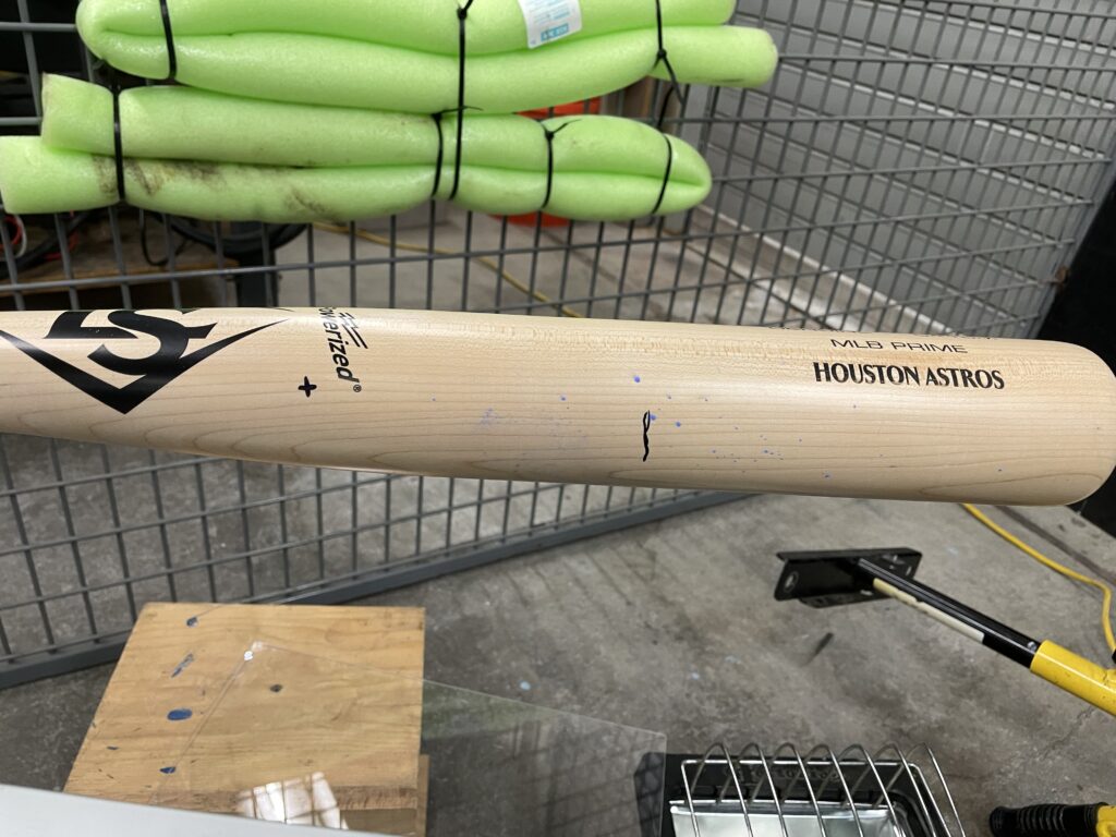
J.J. Ruby – Senior Director of Research and Development for the Houston Astros
Abstract
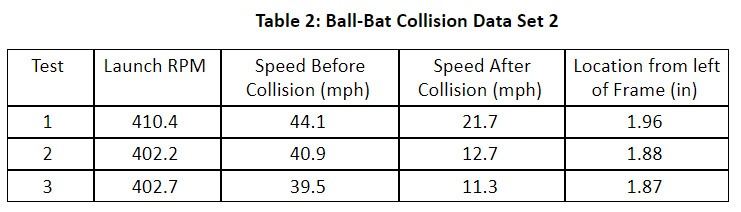
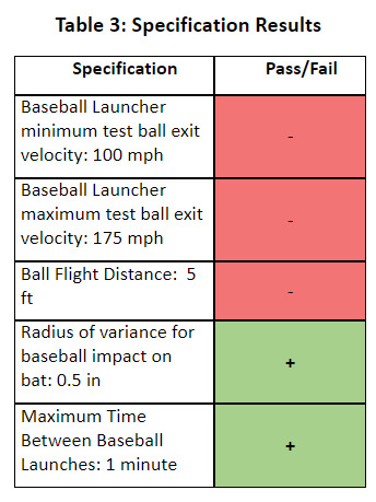
For this project, the team was tasked with designing and manufacturing an apparatus that launches official Major League baseballs into bats at variable speeds. The launcher needed to meet a series of requirements and specifications laid out by the project sponsor. The final design agreed upon consisted of a spinning arm that housed the baseball with a release mechanism triggered by colliding with a steel cylinder extended into the spin path by a solenoid. The final design failed to meet the requirements of launching baseballs between 100 and 175 mph. This was primarily because the combined assembly hit resonant frequency at an arm speed of around 450 rpm, leading to violent vibrations that created too dangerous of an environment to test at greater speeds. Due to the limited field-of -view of the high-speed camera, the design also failed to allow for 5 feet of travel after contact with the bat. At arm speeds under 450 rpm, the baseballs contacted the bat in a radius of variance under 0.5 inches, and a cycle time under 60 seconds was consistently achieved when testing.
Problem Statement
It is unknown how the moment of inertia of a bat affects a bat-ball collision. Measuring the energy transfer between bat and ball will yield useful data for batters. For the Houston Astros, this information can provide insight into which bats are the best for hitters to use in games to yield the best results. This speed range was determined by the combined average bat-ball collision speed in Major League Baseball (MLB) games. Our baseball launcher testing device will help determine the exit velocity of the baseball, therefore finding the transfer of energy between the bat and the ball during collision.
Deliverables, Requirements, and Specifications
Deliverables
- Ball Throwing Device (“Baseball Launcher”)
- Theory of Operation Manual
- Final Report including launcher calibration/variance data
Requirements
- The apparatus must launch official Major League baseballs into a baseball bat at variable speeds
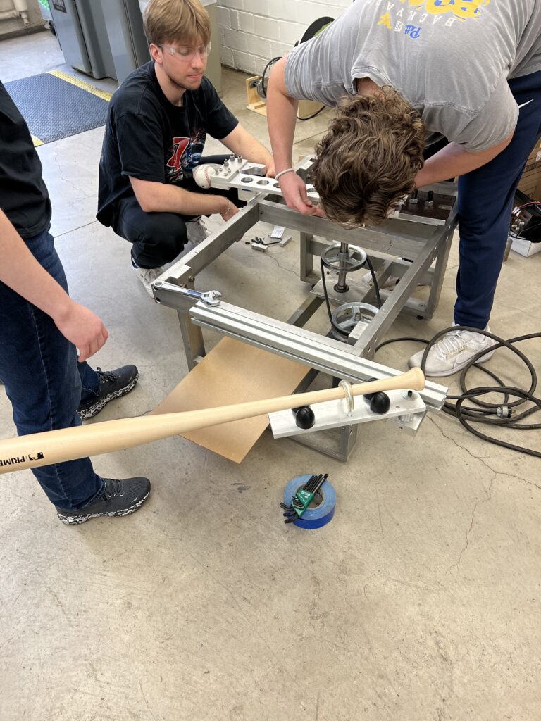
- Approved Major League baseball bats will be used and held stationary during collisions
- A high-speed camera will record the motion of the baseball after impact with the bat
- The apparatus will be non-destructive to the baseballs
Specifications
- Baseball Launcher minimum test ball exit velocity: 100 mph- To be measured by high-speed camera as ball exits launch system
- Baseball Launcher maximum test ball exit velocity: 175 mph- To be measured by high-speed camera as ball exits launch system
- Radius for baseball impact on bat: 0.5 in – To be measured by camera to determine the location of impact
- Maximum Time Between Baseball Launches: 1 minute- To be measured with a time measuring device
- Distance of Ball Fight Pre-Contact: 5 ft- To be measured with a distance measuring device
Design Concept
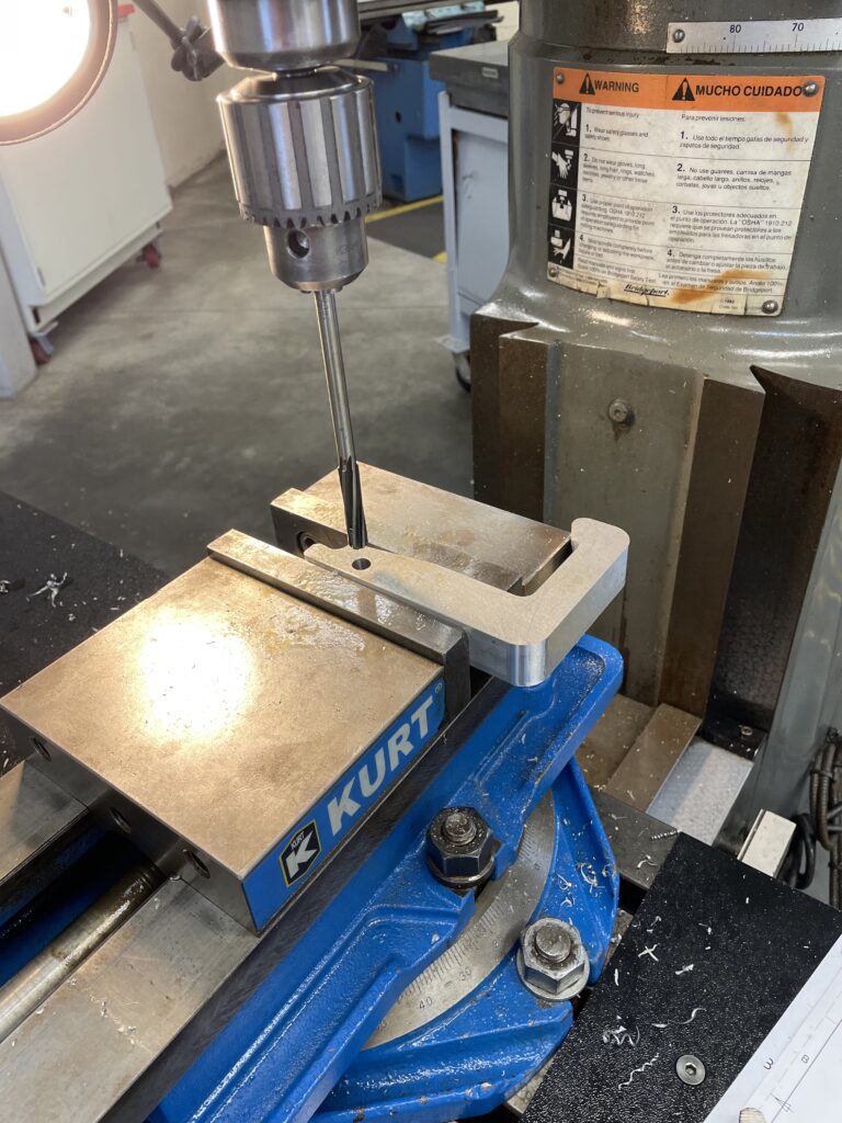
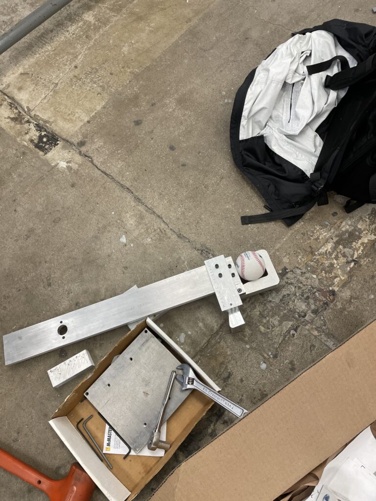
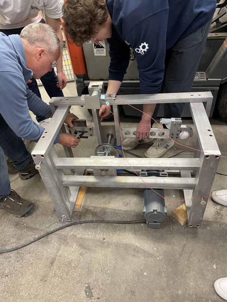
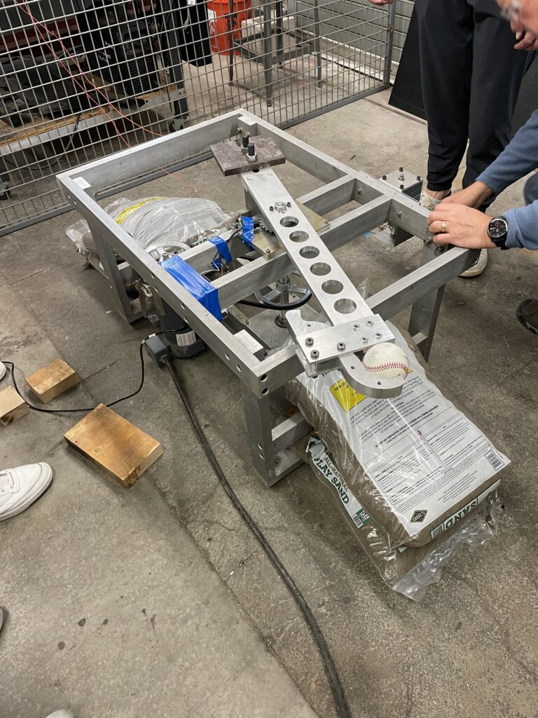
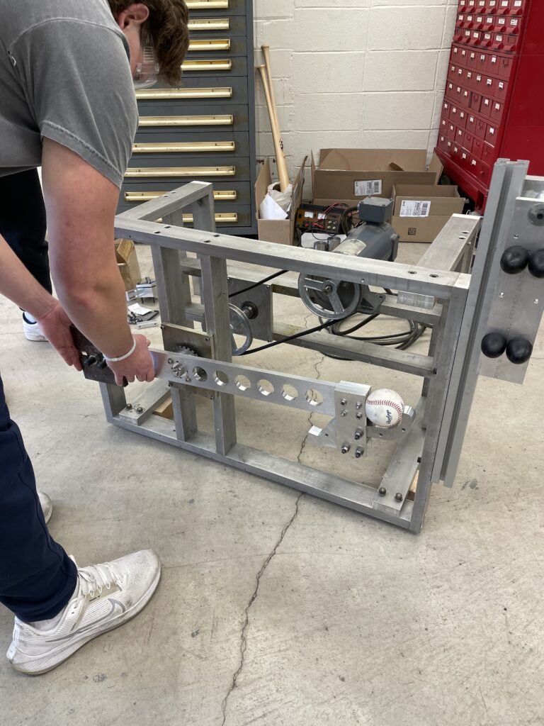
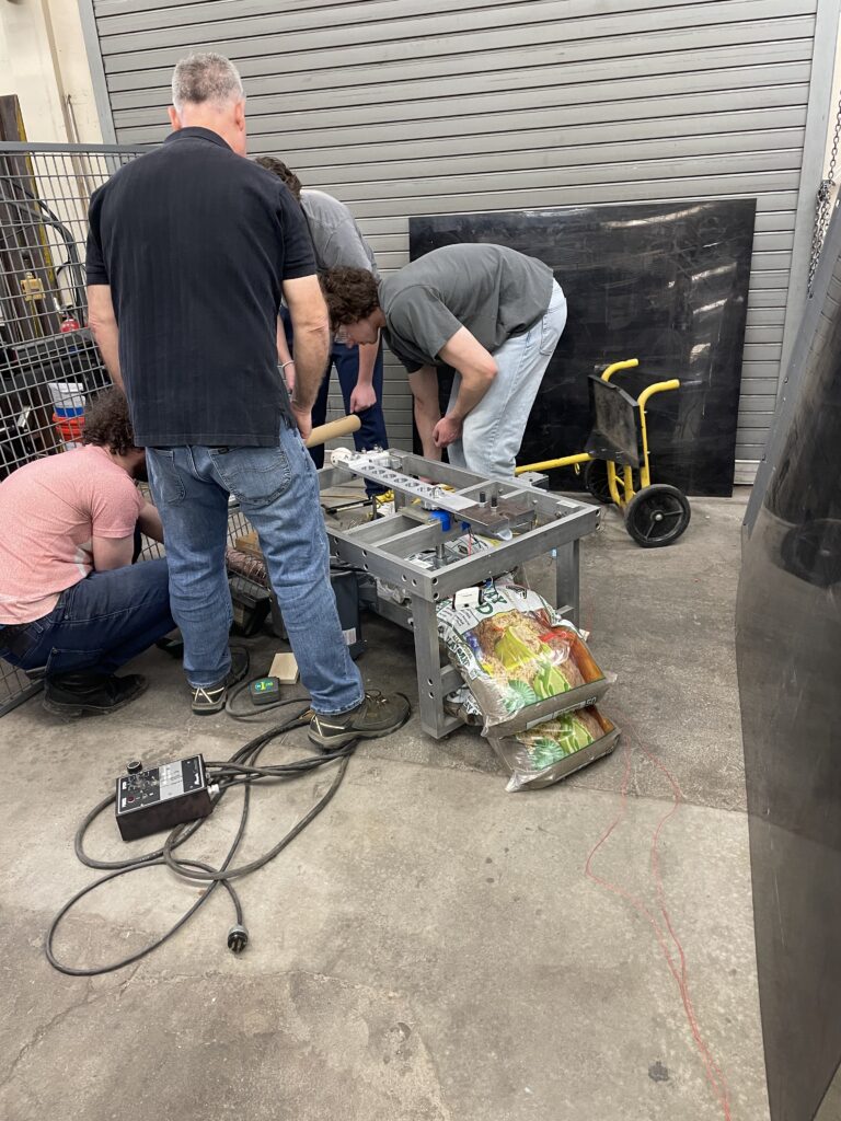
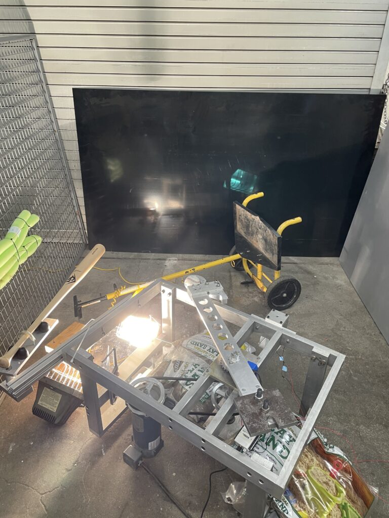
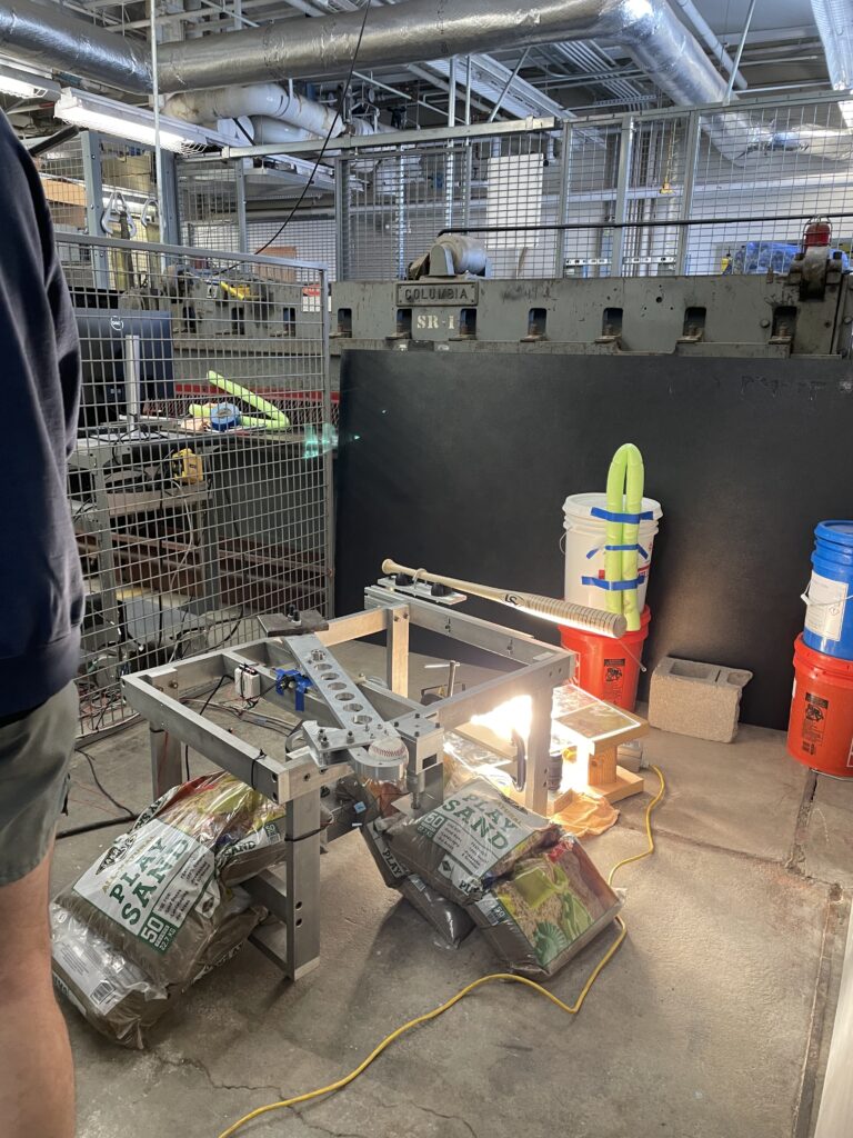
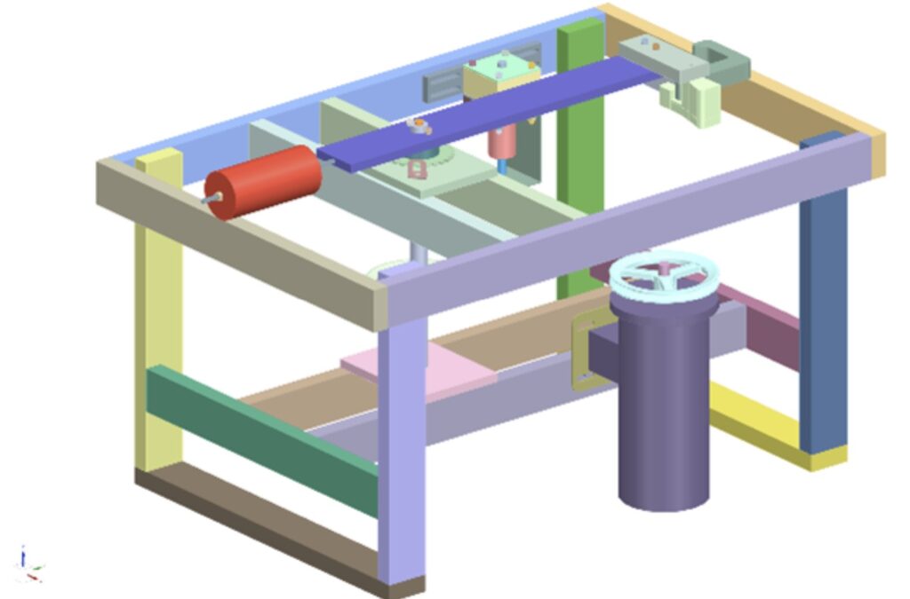
Our design consisted of a rotating arm that threw a baseball at a specified speed proportional to the arm’s rotational speed. To trigger the release of the ball, a solenoid extends a piece of metal that collides with a release mechanism. Following the collision, the release mechanism opens, allowing for the ball to escape.
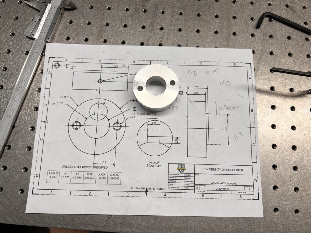
Our design was created using Siemens NX computed aided design (CAD) for the initial design. Finite element analysis (FEA) was then done on the release mechanism of the system to help redesign and optimize the structure before machining even began.
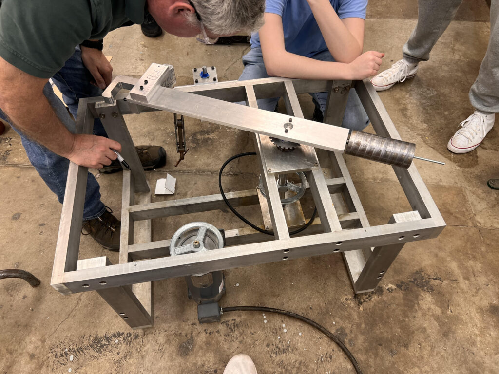
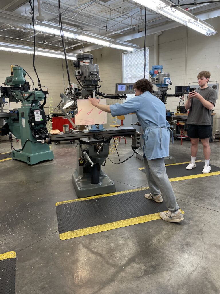
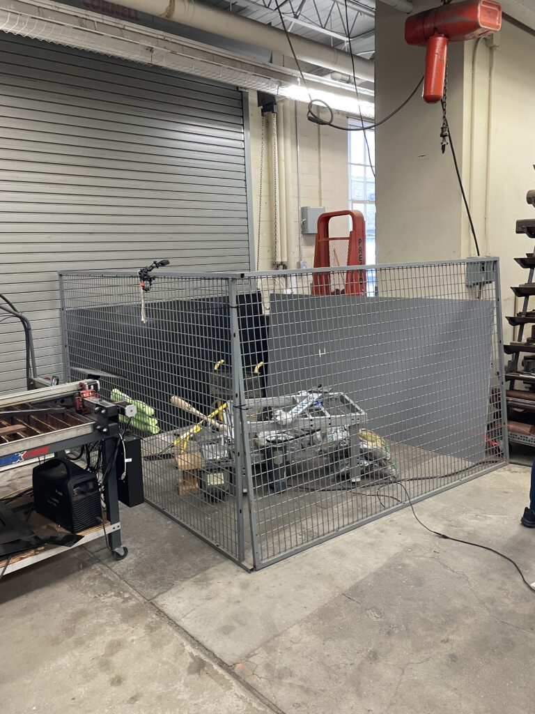
Testing
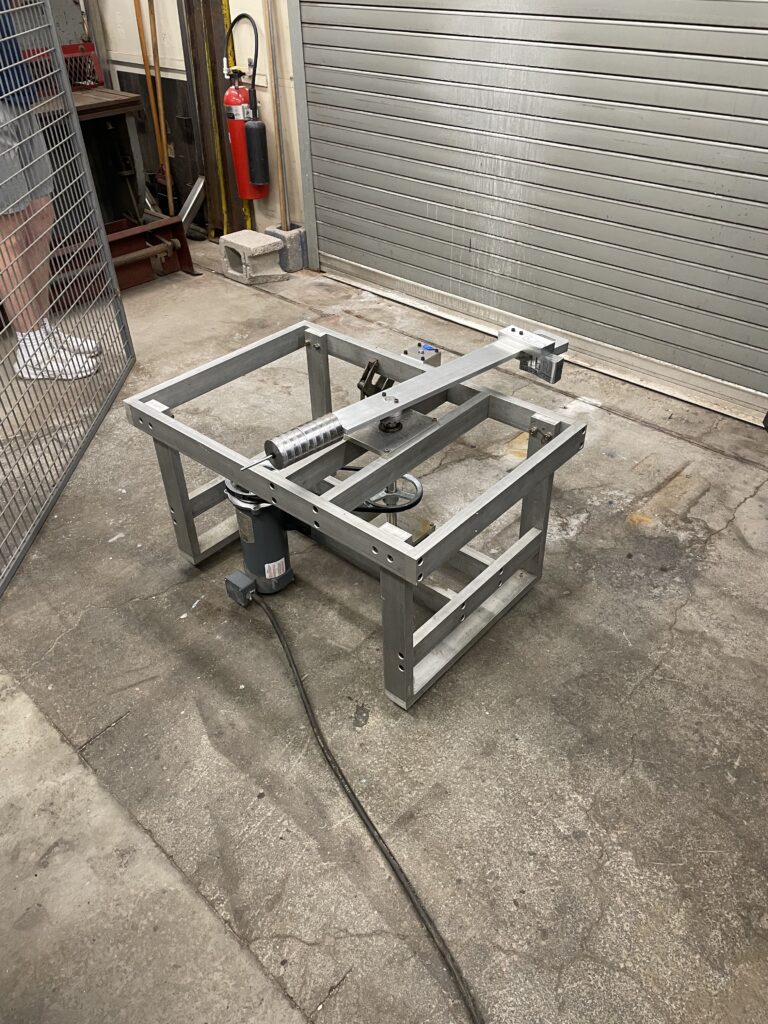
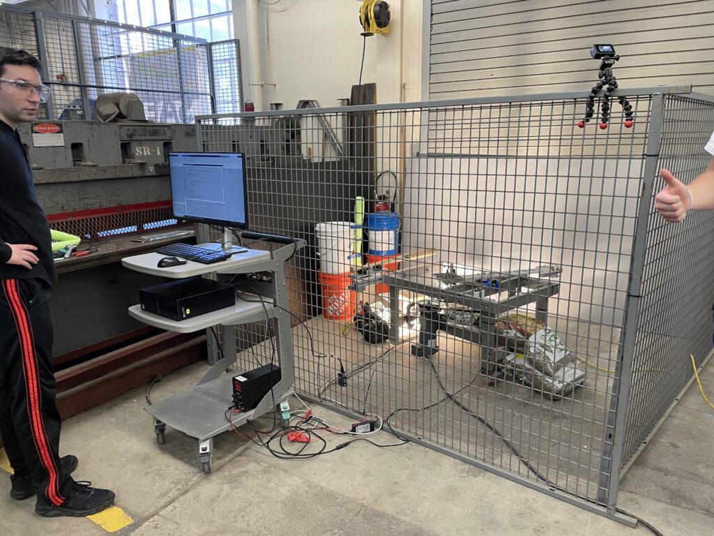
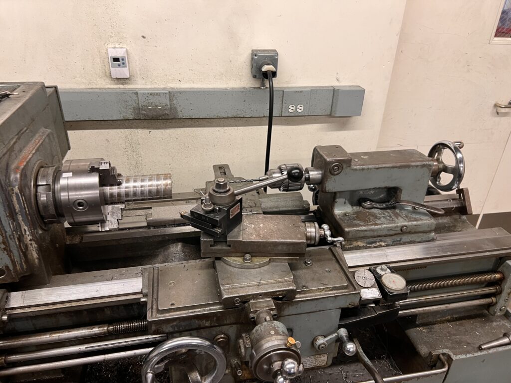
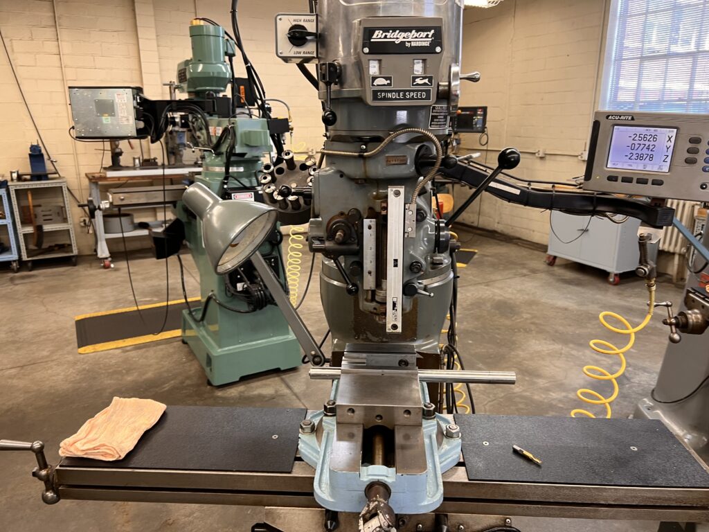
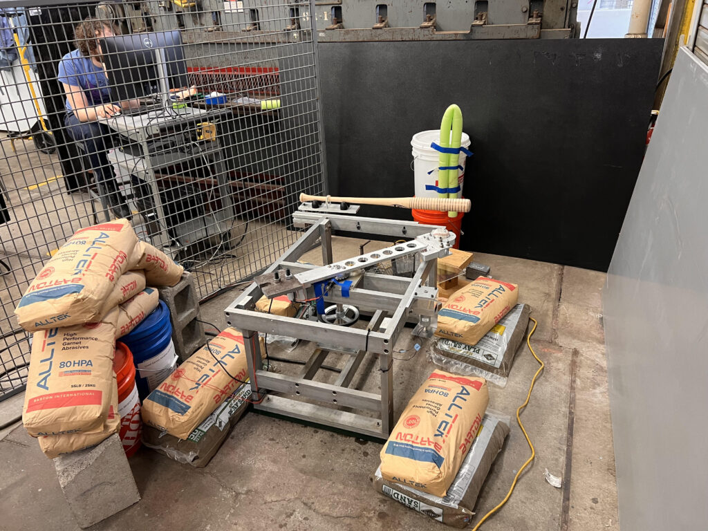
Testing was performed in Taylor Machine Shop on campus. The structure was enclosed using metal cages to provide a layer of safety for those observing. High-speed video was produced for every test allowing for post processing in MATLAB to determine the exit velocity and location of impact for the collision.
Testing gave us great insight into the workings of the system. After the first round of testing, we changed the release mechanism’s design and counterweight. The second round of testing was an improvement on the system from 200 to 450 rpm.
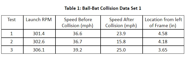
Results
Our design met the specifications for the 0.5 in radius impact location for the bat-ball collision, and the time in between tests could be done in less than a minute. Unfortunately, due to hitting resonant frequency at 450 rpm that caused the structure to begin vibrating, testing was stopped because of safety concerns. This means we did not meet the specifications for both the minimum and maximum launch speeds.
Future Work
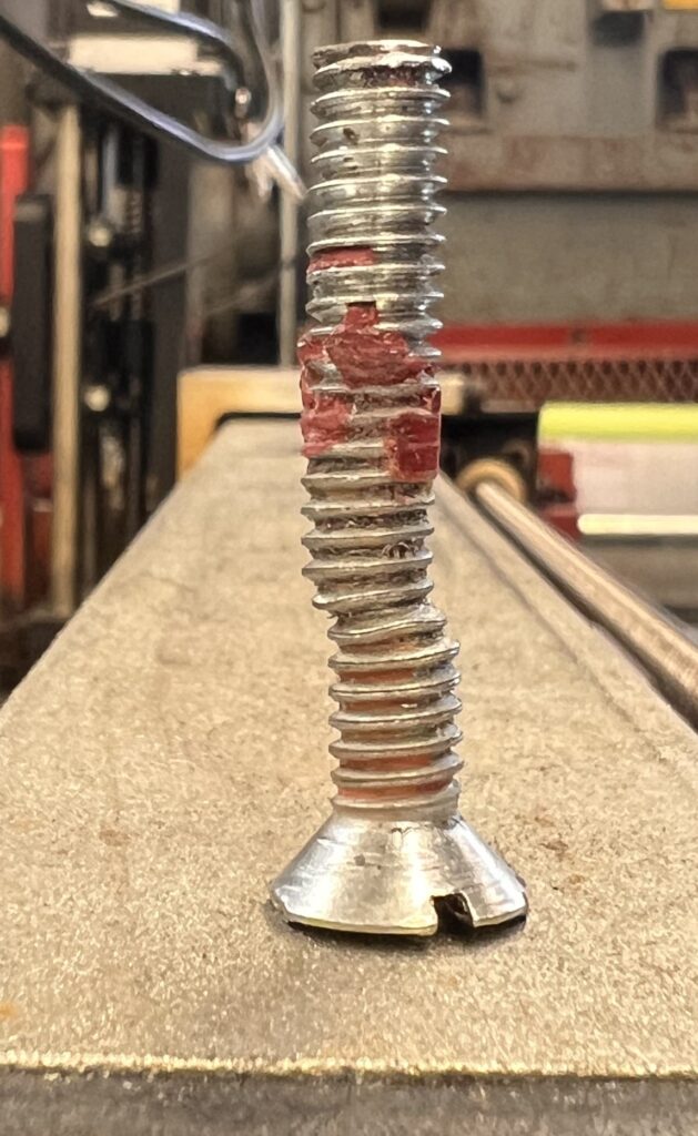
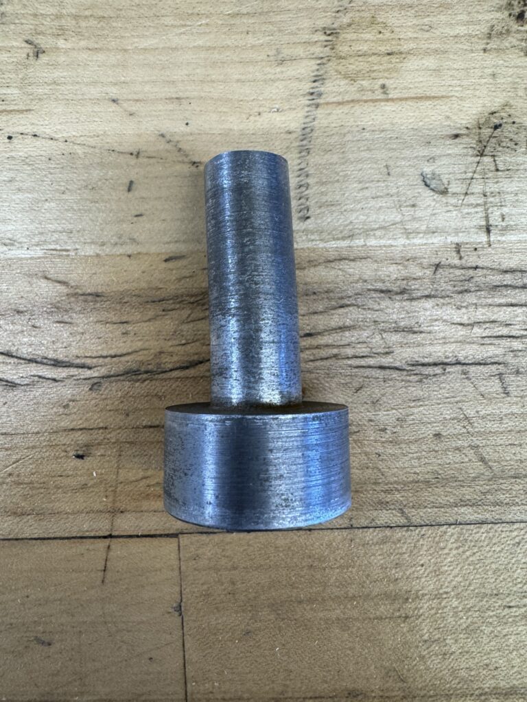
If we had more time to work on this project, our two main goals would be to increase the structural integrity and improve the data acquisition techniques within the system. Given we reached resonant frequency at 450 rpm, a first step would be altering the design so we can safely operate at higher speeds. Separating the bat holder and motor structures would help accomplish this goal, as the bat was the main oscillating component during resonance. The solenoid extender pin was also deformed during testing, causing the team to manufacture extra replacement parts to have on hand. Supporting the solenoid at two points of contact as well as increasing the contact area between the pin and trigger mechanism would improve the lifetime of said components. While high speed video is a great tracking tool, having one camera is a limiting factor. Adding a second camera orthogonal to the current one would greatly improve the accuracy of post processing collision data. To improve data acquisition, switching to a fully Arduino-based system would both improve the efficiency of our analysis as well as reduce the cost of the system. Currently, we are using MATLAB to post-process in collaboration with a National Instruments DAQ; however, neither licensing for MATLAB or the NI DAQ device are cheap. Arduino software is both free and simpler to work with than MATLAB.
Acknowledgements
We would like to thank the following people for their assistance in making this project possible: J.J. Ruby sponsored this project, making our work possible, in addition to providing the initial idea that prompted our design. Professor Muir assisted in designing, manufacturing, and testing throughout the semester. Bill Mildenberger machined numerous parts essential to the functionality of the launcher. Chris Pratt lent her expertise in operating the plasma cutter and the water jet. Sam Kriegsman helped source electronic components and wire the data acquisition devices. Alex Prideaux ordered our parts and configured the high-speed camera. Jim Alkins assisted, oversaw, and provided expertise on numerous components manufactured for the final assembly.
University of Rochester Communications Video
Our group was chosen as one of the groups highlighted for the engineering senior capstone courses. The video they made can be found below.
Team Presentation
Supplementary Materials
Additional Images