Team
- Melanie Earle
- Charles Fleischmann
- Gabriella Gima
- Stelios Halioris
- Christopher Piatek
Mentor
Patrick Ellsworth
Project Overview
Abstract
The aerospace industry has embraced additive manufacturing to increase efficiency and lower the costs of satellite and rocket components. The goal of this project is to design and develop a satellite component known as a Secondary Mirror Support Structure (SMSS) for aerospace company L3Harris Technologies that can be manufactured using additive manufacturing, specifically 3D metal printing. Additive manufacturing will decrease the cost and time it takes to manufacture an SSMS. There were two approaches taken to solve this design problem. The first incorporated topology optimization to find an ideal geometry defined by the requirements and specifications outlined by the sponsor that can be additively manufactured. The second approach used the success of the previous 2022 senior design team’s final SMSS model to influence a new model that focused specifically on the ability of the model to be additively manufactured and the incorporation of lattice acting as an infill for a 3D print. The report will review the design process of the SMSS, the Finite Element Analysis used to analyze the SMSS model, and the items manufactured to support the SMSS design. The final SMSS model in this report passed all the specifications and requirements given by L3Harris and has a final mass of 14.58 lbm.
Problem Definition
Reflector telescopes use a system called Optical Telescope Assembly (OTA), where components such as Secondary Mirror Support Structures (SMSS) are integral to their function. Satellite components should endure extreme vibrations, thermal loads, and accelerations. Components like the SMSS are time-consuming and costly to manufacture with traditional manufacturing methods.
The aerospace industry has embraced additive manufacturing to construct rockets and satellite components to decrease manufacturing time for more launches. L3Harris aims to use metal additive manufacturing to improve the efficiency of traditional manufacturing methods, reduce cost and provide reliable support for the secondary mirror. Using properties of the previous SMSS design, a new SMSS will be modeled and further optimized by analyzing the topology, determining thermal stability, and improving the inner lattice to reduce weight and overall cost.
Requirements, Specifications, and Deliverables
Requirements
- The project scope is the design, analysis, and prototype of the SMSS only.
- The project will focus on additive manufacturing solutions to the problem statement.
- The SMSS will have interfaces for and support the Secondary Mirror and Mounts, Actuator Assembly, Shade Assembly, Misc. Thermal Hardware.
- The design will be producible with additive manufacturing methods.
- The following design factors of safety will be used:
- Yield: 2.0
- Micro-yield: 1.0
- Ultimate: 2.5
- Buckling: 4.0
- Mass Contingency factors will be used
- Concept Design: 20%
- Preliminary Design: 15%
- Final Design: 10%
- Post Final Design
- 5%, Measured Hardware: 0.10%
- There shall be no trapped cavities in the SMSS.
Specifications
- The outer diameter of the SMSS must be 48 ± 0.005″.
- The SMSS will interface with the Forward Metering Structure at three locations 120 degrees apart.
- The first frequency mode of the SMSS shall be 120 Hz or greater when grounded at the FMS interface and supporting all hosted hardware.
- The goal mass is a maximum of 18 lbm.
- The SMSS shall have positive margins of safety against yield and ultimate failure when exposed to a quasi-static load of 12G laterally and 18G axially simultaneously, (lateral swept 15 deg increments) combined with a 5C to 35C temperature range (nominal room temp is 20C) while supporting all hosted hardware.
- The SMSS and hosted hardware shall not obstruct more than 14% of the Primary Mirror (PM) clear aperture area (assume 1.1m diameter clear aperture).
- The SMSS should provide a stable mounting platform for the Secondary Mirror in thermal environments. The average motion of the SM interfaces under a 1-degree C isothermal load should be 0.66 micro-inches translation (RSS of X and Y) or less and 0.037 micro-radians rotation (RSS of Rx and Ry) or less.
Deliverables
- A Finite Element Model of the Secondary Mirror Support Structure in Nastran.
- CAD file prototypes and 2D drawings of the Secondary Mirror Support Structure.
- A Technical Report
- Host design review meetings and provide supporting slides for L3Harris Sponsor. Three meetings will be a Concept Design Review, Preliminary Design Review, and Final Design Review. CAD and FEA analysis will be presented and provided at these meetings.
- 3D Printed Prototype of Secondary Mirror Support Structure which can be scaled and composed of materials other than Invar-36.
- Model validations will be included in the final technical report and provided at design review meetings. These model validations will be conducted through simulations and experimental data.
Concepts
Model Optimization
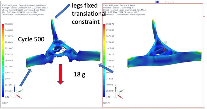
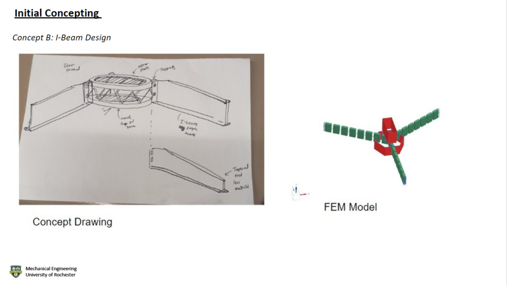
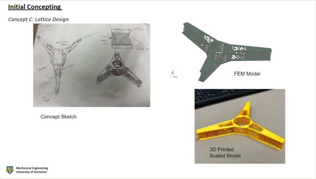
The team took two approaches to the design problem. The first was topology optimization. L3Harris turned to additive manufacturing to have a more efficient and lower-cost satellite component manufacturing process. Topology optimization removes redundant material from a component by considering the loads, conditions, and boundaries of a component, reducing the overall costs and time of production. The second approach that was taken to the design problem was using last year’s design as an influence on a new design. The first thing our team implemented was an interior lattice within the design. An interior lattice, instead of using a traditional printer infill, would allow for less material to be used while using additive manufacturing and retaining the stiffness of the structure.
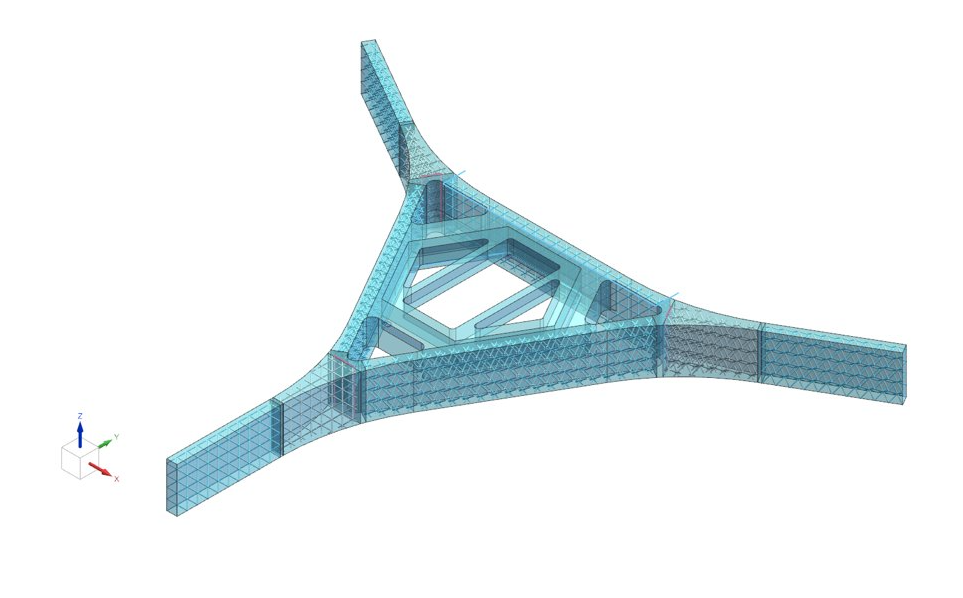
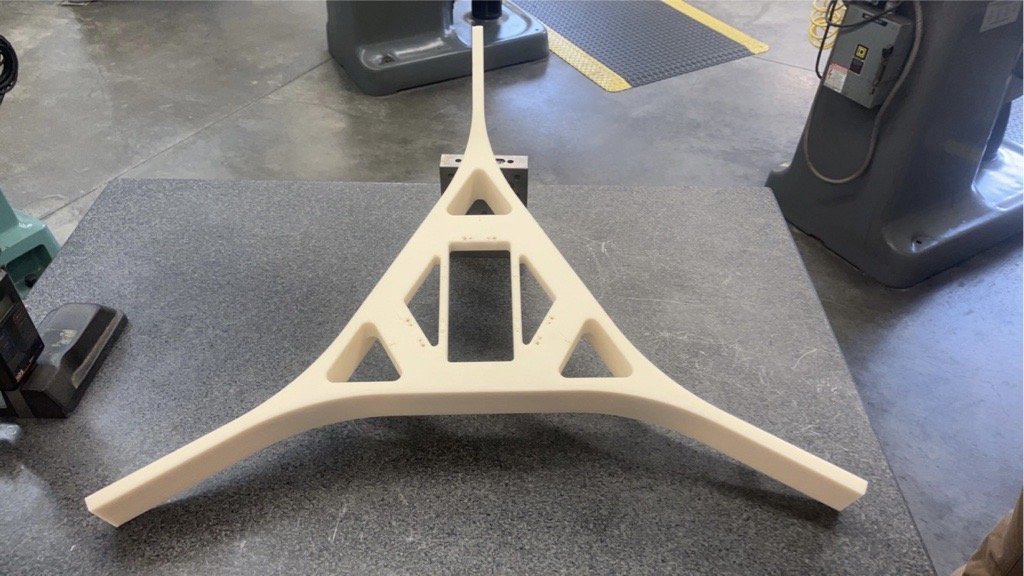
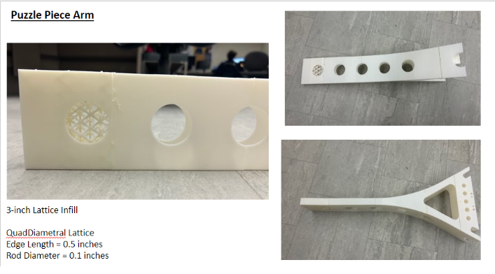
The second contribution from the previous year’s design is taking the topology optimization that was conducted last year, which showed where redundant material would be on the SMSS with the loading requirements provided. This approach started with a model which included interface mounting features where the SMSS would interact with other pieces of hardware within the satellite. Then, using the previous year’s model, redundant material was cut from the design, resulting in the second iteration. From the second iteration, an interior lattice was incorporated into the design, where the interior of the second iteration was shelled out to reduce weight and replaced with an interior QuadDiametal lattice. These dimensions are changed in later models to try and optimize the weight of the structure.
Mechanical Analysis
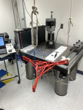
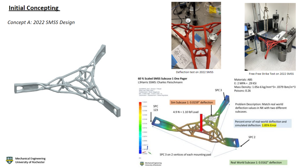
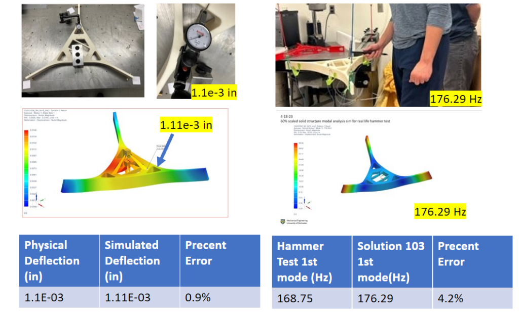
The first step the team took in this project was comparing last year’s physical prototype to a Siemens NX simulation of concept A. This allowed for a stronger comprehension of the design problem and an understanding of where last year’s design was successful. The two tests conducted include a deflection and a free-free strike modal test to compare the physical prototype and the simulation. The deflection test had a percent error of 1.85%, and the modal hammer test had a percent error of 1.02%, validating the simulations.
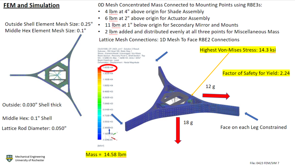
For simulation analysis, the model was split into different bodies to input a lattice with different orientations in the varying sections of the structure. The material Invar-36 was used due to its low coefficient of thermal expansion. The internal lattices have a rod diameter of 0.05″ and are connected to the inside faces using 1D Mesh-to-Face RBE2 connections. While this may add artificial stiffness, running a convergence study will reduce this effect. A 2D thin shell mesh was added over the entire model. The thickness of the split middle hexagon shell is 0.1″ while the rest of the model was reduced to have a 0.03″ shell thickness. The overall mass was cut to 14.58 lbm. The hardware interfaces were modeled as 0D mesh concentrated masses and were connected to the mounting points using RBE3 connections. The highest Von-Mises stress of this model has a factor of safety of 2.24 below yield.
Manufacturing
The main goal of this project is to additively manufacture a Secondary Mirror Support Structure. Every design decision made during this project considered how it could affect the additive manufacturing process of the SMSS. A true additively manufactured SMSS would be 3D printed using Invar-36, a metal with a very low coefficient of thermal expansion (CTE), which is favorable as it will avoid significant expansion and contraction of the SMSS in launch weather and in space. A full-scale model would not be able to be printed due to the limitations of the metal 3D printers the team has access to and the significant cost of printing a whole SMSS. Because of these limitations, the team decided to have a model printed in plastic at 60% size and with a solid infill.
The team ultimately chose Xometry to manufacture the part, due to its ability to give the team instant quotes for models, the capability to 3D print with metal materials, and the relatively low fabrication and delivery times compared to other companies. With expedited shipping and the team unable to get tax exemption on the order, the price for the 60% model came to be $601.58, arriving with enough time to allow us to run hammer and deflection tests. The second idea would allow the team to showcase the lattice infill of the SMSS model, which is a significant design feature that would be missing from the third-party 60% scaled solid infill model. This idea revolved around using the printers located on the University of Rochester campus and breaking the SMSS model apart into pieces that could fit on the print beds of the 3D printers on campus. The pieces would then be glued together after they were printed, to display what the interior lattice design would physically look like.
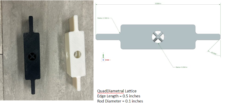
Due to the time it would take to print the full model and the amount of filament that would be used to print the full model, the team decided to print a single arm scaled to the original model size. The final piece that was manufactured for this project was a test coupon which would allow the group to analyze the stiffness of lattices used within the SMSS using an MTS.
Testing and Results
| Specification | Pass/Fail | Requirement | Pass/Fail | |
| 1 | Pass | 1 | Pass | |
| 2 | Pass | 2 | Pass | |
| 3 | Pass | 3 | Pass | |
| 4 | Pass | 4 | Pass | |
| 5 | Pass | 5 | Pass | |
| 6 | Pass | 6 | Pass | |
| 7 | Fail | 7 | Pass in Future Iterations of Model |
Societal and Environmental Implications
A review of metal additive manufacturing written in 2021 estimated that due to the increase of additive manufacturing within the aerospace industry, the market will increase to $3.187 billion by 2025. Coupled with the significant increase in rocket launches, additive manufacturing is rapidly becoming a choice method of fabrication in the aerospace industry. Improving upon this technology will only strengthen the industry as a whole, boosting infrastructure in telecommunications, the internet, and the capacity for extraterrestrial interests. The environmental impact shows more negative impacts with additive manufacturing having a carbon footprint ten times the size of traditional manufacturing with a higher energy consumption rate. Because of this, methods like topology optimization and using materials with lower melting points could decrease the amount of energy, and the material needed could be reduced.
Recommendations for Future Work
Further simulations should be run to understand how the SMSS is thermally expanding under the current simulation conditions, and what could be done to improve the SMSS considering specification 7 and pass in the future. An oven test could provide the opportunity to understand what stress occurs due to thermal expansion and contraction. For the oven test to be conducted, a 3D metal-printed scaled model of the SMSS would have to be manufactured. t may not be possible to use Invar-36 as the chosen material for a scaled model of the SMSS, but it would be beneficial to find an accurate cost of a full-scaled SMSS model manufactured using 3D printing with Invar-36 as the selected material.
One area for future work is a continued effort to research and develop the lattice, with the intention of creating a test coupon manufactured with metal as the material. The metal test coupon would allow for a further understanding of how the lattice can improve the stiffness of the SMSS, and a comprehension of if the added mass from the lattice to the SMSS is a worthwhile investment. In terms of the SMSS itself, the creation of venting holes would need to be added to the SMSS, so there are no trapped cavities on the model, which would allow us to fulfill all the requirements provided by L3Harris. A convergent study should be considered to find the optimal element mesh size for the FEA, which will help with 1D mesh-to-face RBE2 connections. Finally, future work should take advantage of the symmetry of the model, so that when there is a finer element mesh size, the simulations will have a faster run time.
Based on the hundreds of cycles run for topology and the optimum design being found towards the end of the runs, more cycles may be run to find a further optimized design from topology. It would be recommended that the topology should be run for at least 1000 cycles to allow an analysis of a properly converged model. The constraints used within topology use estimated best values in terms of the minimum size of members and overhang angles which could be toggled and optimized individually to obtain more optimal sizing.
Acknowledgments
The L3Harris team would like to show our gratitude and give thanks to the sponsor of this project, Patrick Ellsworth, Chris Pratt, Mike Pomerantz, Jim Alkins, Bill Mildenberger, Paul Osborne, Alex Prideaux, Lyrica Yanaway, along with a special thanks to Professor Muir for his continued help throughout the duration of the project.