Secondary Mirror Support Structure (SMSS) is a mount used in some large telescopes for holding optical mirrors. These structures must be highly durable and require precise manufacturing methods. Increased durability and precision come at the cost of increased expenses and time, and as such, L3Harris is looking into additive metal manufacturing to potentially reduce manufacturing time while increasing production capacity.
Team Members
(From left to right)
Kaitlyn Bartlett
Angel Bermudez
Matthew Stead
Stanley Huang
Joshua Nova-Yingst

Abstract
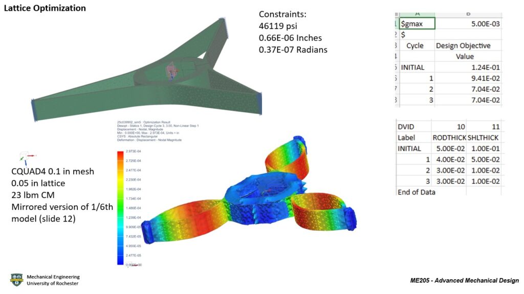
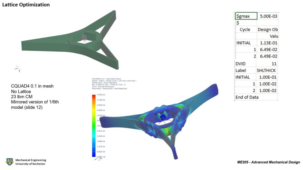
Lattice structures are created by repeating unit cells in carefully designed and optimized patterns, allowing for weight reduction while maintaining the ability to withstand stress and loads from the environment. With advancements in additive manufacturing, the ability to produce these structures with minimal material waste and lower costs has made them increasingly valuable in the aerospace industry, where a high strength to weight ratio is essential. The goal of this project is to find out the best lattice configuration for the structure of a Secondary Mirror Support Structure (SMSS) that can be effectively fabricated with additive manufacturing in metal materials. To meet the goals of this project, the team took inspiration from last year’s accomplishments to help form our initial concept designs and implement them with lattice eventually. A series of lattice, geometry, and topology optimizations were conducted to further improve our designs towards meeting the requirements and specifications. Using the designs from last year as references, our team focuses mainly on optimizing internal lattice structures in a model with a combination of different dimension meshes rather than improving the load-bearing geometry of the structure. This report will highlight the iterative design process, finite element analysis, manufacturing and testing, and supporting analysis data. These techniques and results combined to create a model that meets all the provided requirements and specifications.
Project Details
Requirements
- The design and analysis of a SMSS model as well as a physical prototype.
- The model must be 3D-printable in titanium or invar, and it must be able to hold 23 pounds of equipment.
- The SMSS shall interface to the Forward Metering Structure (FMS) at three locations 120 degrees apart.
- The SMSS shall provide interfaces with and support the Secondary Mirror and its mounts, the Actuator Assy, the Shade Assy, and all necessary thermal hardware.
- There shall be no trapped cavities, and the entire structure must be considered “precision cleanable” by L3Harris metrics.
- The following factors of safety shall be used in analysis:
- Yield Stress: 2.0
- Micro-Yield Stress: 1.0
- Ultimate Stress: 2.5
- Buckling Stress: 4.0
- The following mass contingency factors shall be used:
- Concept Design: 20%
- Preliminary Design: 15%
- Final Design: 10%
- Post-Final Design: 5%
- Measured Hardware: 0.10%
Specification
| Description | Method of Evaluation |
| 1. The outer diameter of the SMSS (interface to the FMS) shall be 48 inches | NX sketch of a 48-inch circle around the model |
| 2. The first mode of the SMSS shall be 120 Hz or greater when grounded at the FMS interface and supporting all hosted hardware | NASTRAN Solution 103 Modal Analysis |
| 3. The mass of the SMSS shall be 18 lbm or less | NX Solid Model Properties |
| 4. The SMSS shall have positive margins of safety against yield and ultimate failure when exposed to a quasi-static load of 12 G laterally and 18 G axially simultaneously (lateral swept 15-degree increments) while supporting all hosted hardware | NASTRAN Solution 101 Linear Statics |
| 5. The SMSS shall have positive margin of safety in a 5°C to 35°C temperature range while supporting all hosted hardware | NASTRAN Solution 101 Linear Statics |
| 6. The SMSS and the hosted hardware shall not obstruct more than 14% of the Primary Mirror (PM) clear aperture area of 1.1 meters diameter | NX Solid Model Properties |
| 7. The average motion of the SM interfaces under a 1 degree C isothermal load should be 0.66 micro-inches translation (RSS of x and y) or less | NASTRAN Solution 101 Linear Statics |
| 8. The average motion of the SM interfaces under a 1 degree C isothermal load should be 0.037 micro-radians rotation (RSS of Rx and Ry) or less | NASTRAN Solution 101 Linear Statics |
Project Highlights
Concepts
The L3Harris team developed 3 main concept designs for the SMSS with two new designs and one being last year’s model.
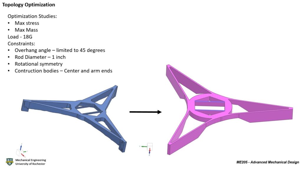
Design 1 is the final model presented by the previous team and is used as the baseline for the other 2 concepts described below. This design incorporates a circular center to reduce weight and the area of obstruction for the field of view. Also, the legs of the structure interface tangent to the circular center to combat the translation and rotation of the structure in and about X and Y axes when thermal loads.

Design 2 was designed under the concept of effectively distributing load throughout the continuously curved strut. From the single rectangular cross section with a width of 0.8” at the end of the strut where the mounting points are, it splits into two sections with 0.67” width each. The strut continues in a constant radius of curvature to merge with the other half of the other strut, forming three continuous curves.

Design 3 was made with the intention of maintaining the uniform displacement from the isothermal load while improving stiffness and increasing resistance to vibration. The design is radially symmetrical but still has the beams meet at the outer edge of the mounting points so that the forces are distributed in a similar manner to last year’s design but, in this case, the beams extend on both sides of the external mounting point (where the SMSS connects to the satellite).

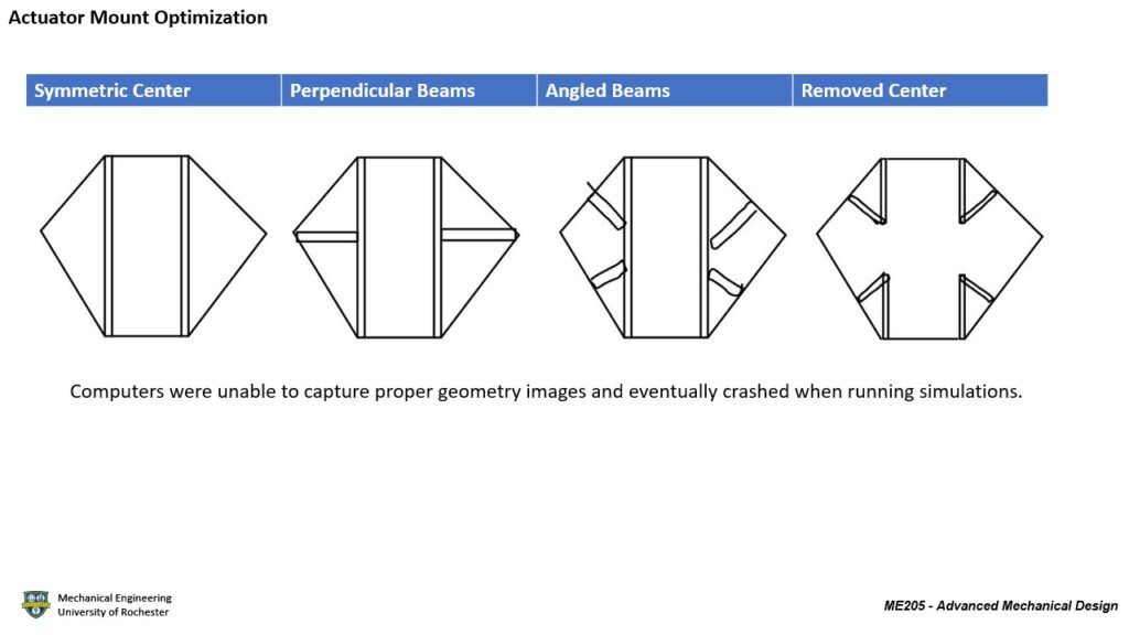
Initial Design Progression

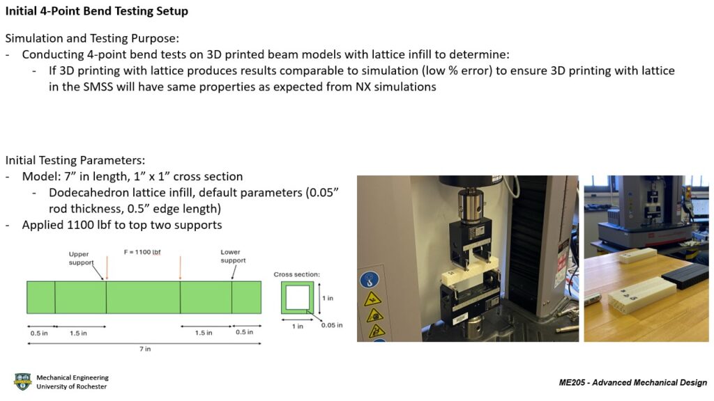
Manufacturing
Fused Deposition Modeling (FDM)
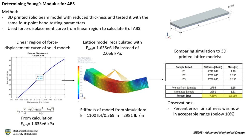
Test coupons – ABS, PLA


Power Bed Fusion (PBF)
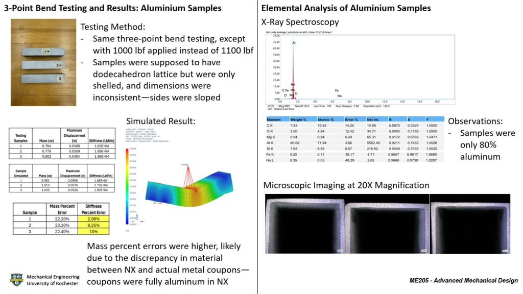
Test coupons – Aluminium
Final scale model – Aluminium


Testing and Analyzing
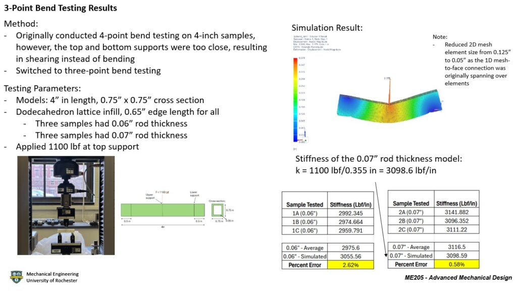
Coupon Testing and Results
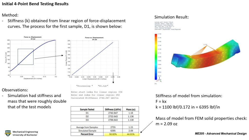
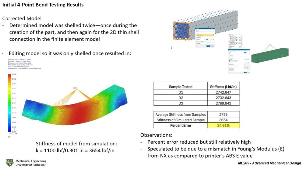
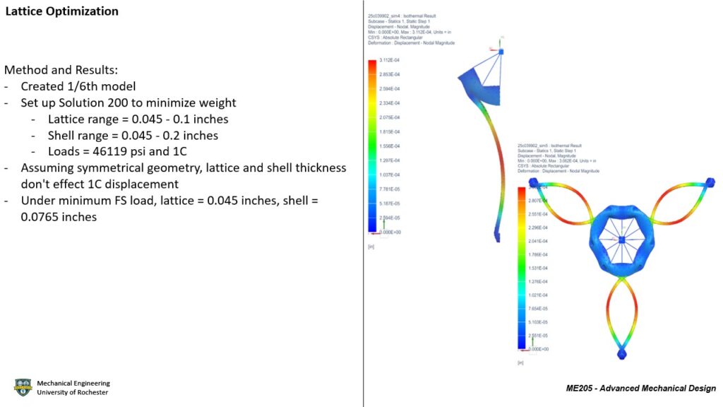
Optimization
Model Analysis
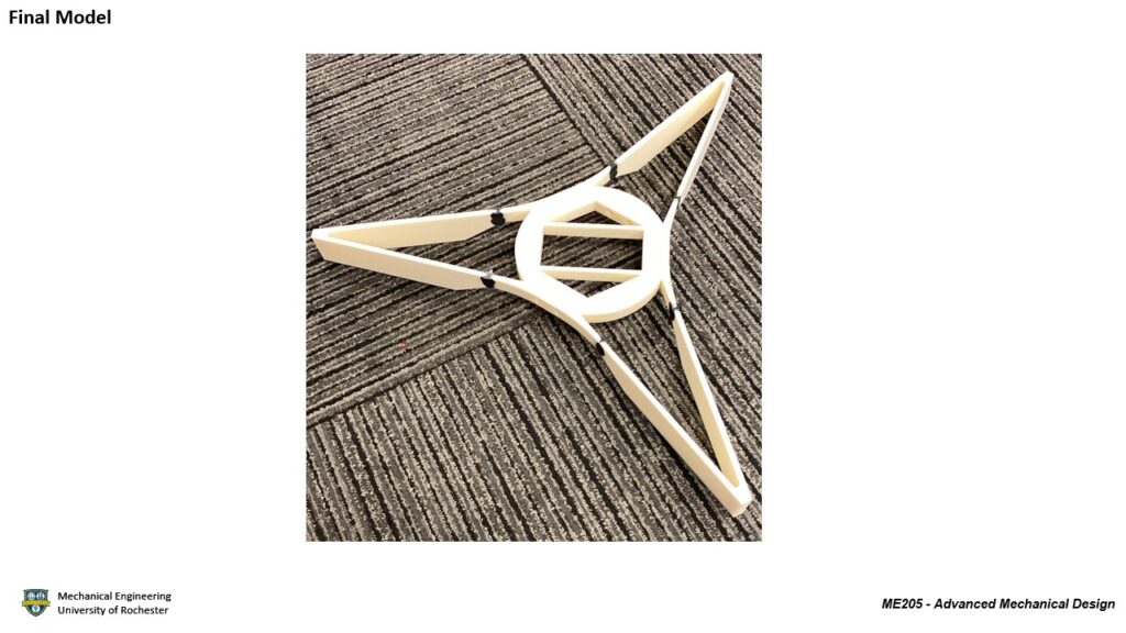
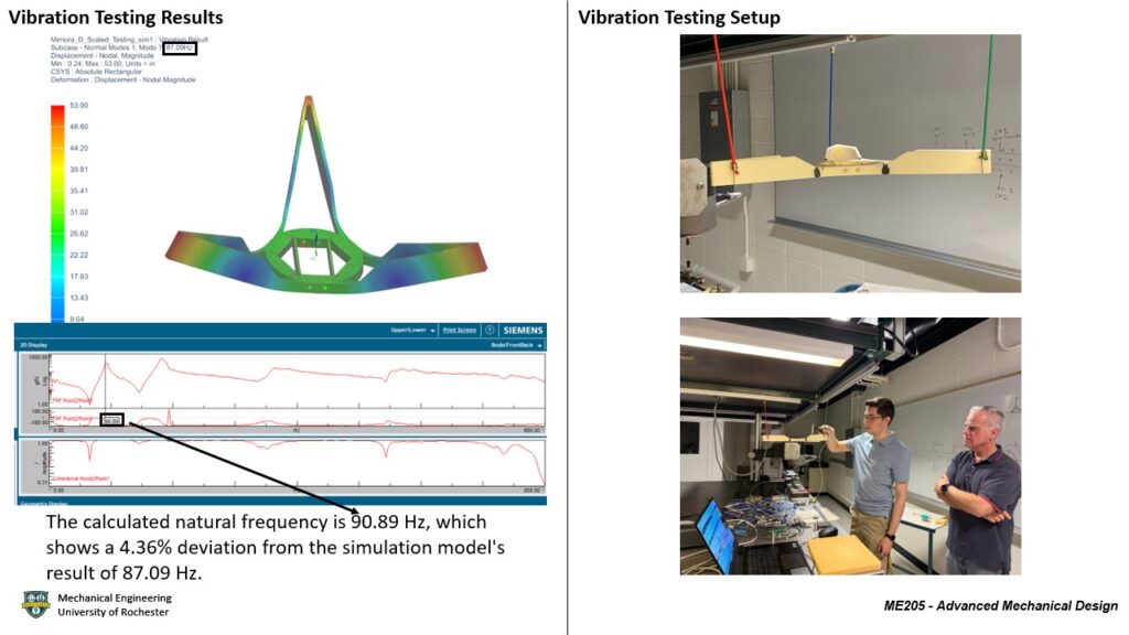
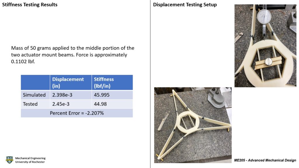
Final Model and Testing
Project Conclusion
| Requirements and Specifications | Verification |
| 1. The outer diameter of the SMSS (interface to the FMS) shall be 48 inches | All geometry is contained within 48-inch diameter circle. PASSED |
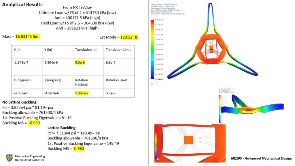
| 2. The first mode of the SMSS shall be 120 Hz or greater when grounded at the FMS interface and supporting all hosted hardware | The 1st mode of vibration is 120.12 Hz PASSED |
| 3. The mass of the SMSS shall be 18 lbm or less | The mass is 16.9 lbm PASSED |
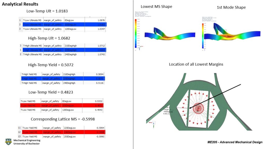
| 4. The SMSS shall have positive margins of safety against yield and ultimate failure when exposed to a quasi-static load of 12 G laterally and 18 G axially simultaneously (lateral swept 15-degree increments) while supporting all hosted hardware | The lowest MS of the shell is 0.48 and the lattice MS is –0.59 PASSED |
| 5. The SMSS shall have positive margin of safety in a 5°C to 35°C temperature range while supporting all hosted hardware | The above MS used the temperature range PASSED |
| 6. The SMSS and the hosted hardware shall not obstruct more than 14% of the Primary Mirror (PM) clear aperture area of 1.1 meters diameter | The SMSS has 12.5% coverage PASSED |
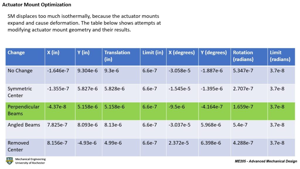
| 7. The average motion of the SM interfaces under a 1 degree C isothermal load should be 0.66 micro-inches translation (RSS of x and y) or less | Average motion is 9.3 micro-inches FAILED |
| 8. The average motion of the SM interfaces under a 1 degree C isothermal load should be 0.037 micro-radians rotation (RSS of Rx and Ry) or less | Average motion is 0.54 micro-radians FAILED |
Future Work
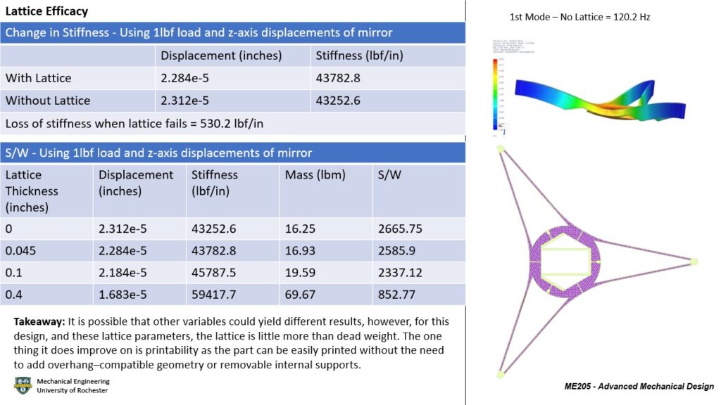
- Teams should carefully evaluate the trade-off for the internal lattice. Increased stiffness and printability vs reduced strength-to-weight ratio.
- Earlier communication with vendor – improve understanding of infill density, build orientation, lead times, printer limitations and material additives.
- Further optimization into 2024 L3Harris team’s design, learning from their successes, improving the geometry, and printability but utilizing the existing shape.
- Future iterations could focus on the geometry at the actuator mounting beams of the SMSS and may benefit from simulations and tests targeting that area.
Acknowledgements
The 2025 L3Harris Team extends appreciation to Patrick Ellsworth, Patrick Zinter, Steve Sutton, and L3Harris for their sponsorship, valuable feedback, and guidance throughout the duration of the project. The team would also like to acknowledge Professor Christopher Muir for teaching the team the necessary skills to complete the project. The team would also like to acknowledge the efforts of Christine Pratt for the numerous MTS machine testing sessions as well as analyzing the metal coupons via mass spectrometry. Lastly, the team would like to thank Jim Alkins for his support in 3D printing the test coupons as well as the plastic scaled SMSS model. All contributions were vital to the completion of the project, and the team is deeply grateful for the efforts of all involved.