A Low-Cost Underwater Acoustic Detection and Release System that detects 37.5 kHz acoustic pinger signals and triggers a mechanical release, designed for search and recovery applications.

[Fig. 1 – Project team]
Abstract
This project focuses on developing a cost-effective underwater acoustic pinger detector as an alternative to expensive commercial systems. Underwater acoustic pingers, commonly used in applications such as aircraft black box recovery and search-and-rescue operations, emit standardized signals (37.5 kHz) to aid in locating submerged objects. However, existing detection systems are often costly and not easily scalable, limiting accessibility for broader or distributed deployments. To address this challenge, the proposed solution is a compact, low-cost detection system capable of identifying and responding to a 37.5 kHz acoustic signal. The final prototype shows reliable detection and release operations, proving the project to be a success.
Team
Acknowledgments
We are sincerely grateful to Professor Jack Mottley, Professor Daniel Phinney, and Professor Irving Barron Martinez for their patient guidance and feedback throughout this project. We also thank those in the ECE purchasing department for their help in ordering the parts for our project.
Introduction & Project Overview
The airplane “black box” is a widely known device that aids rescue operations in the event of a plane crash. Upon hitting the water, a component called a “pinger” in the black box starts sending an underwater signal, allowing pinger detectors to pick up the signal and alert rescue teams. In order to use this device, rescuers must tow it in the water and circle around the site of the crash, costing the teams time, fuel, and manpower. An alternative to this arduous process would be a pinger detector that is easily reproducible, such that many such devices can be dropped in the water and used to detect the signal.
The project goal was to develop an underwater acoustic pinger detector that is cost-effective, portable, and easily accessible. Current underwater acoustic pinger detectors available in the market are large and must be towed around by a rescue team. As these existing detection products are often costly and unwieldy, it would be ideal to have a pinger detector that can be dropped in the water, sink to the bottom of the ocean, detect the signal, float back up to signify the location of the signal detection, and be discarded afterwards. The challenge presented to us was to design and implement a pinger detector that is cheap, lightweight, easy to produce, and eco-friendly, such that thousands of them could be released in the event of a crash and be able to quickly detect a pinger signal.
To address this challenge, a compact, low-cost detection system was designed. It is capable of identifying and responding to a 37.5 kHz acoustic signal, simply by being dropped in water and rising back up upon signal detection. The design leverages readily available electronic components to perform signal acquisition, amplification, filtering, and decoding, followed by a microcontroller-controlled actuation mechanism. Upon successful detection, the system triggers a servo-based weight release mechanism, enabling an easily visible automated response by allowing the device to float back to the surface. In a real-life application, the visual signal of the pinger detector rising back to the surface would indicate to rescuers that the pinger has been detected.
Components
For this prototype, the following components were chosen. In future versions, the microcontroller may be replaced with a discrete logic-based processing system to reduce cost.
- Piezoelectric transducer
- INA2128 Dual Instrumentation Amplifier
- LM567CN Tone Decoder
- LMC555 Timer
- MT3608 DC-DC Converter
- BOB12009 Logic Level Converter
- PIC32MX110F016B – I/SP Microcontroller
- Servomotor with Latch
- Metal weights and Steel wire
- 3.2V Lithium-ion Battery
- Battery holder
- PCB – Fiberglass epoxy with copper traces
- PLA casing – 3D printed
- Gorilla Epoxy glue and Caulk seal
Circuit Design
System Overview
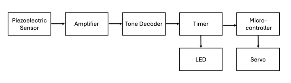
The system is designed as a signal processing chain that converts acoustic input into a mechanical response. A piezoelectric transducer captures the 37.5 kHz pinger signal, which is amplified, frequency-filtered, and processed to trigger a release mechanism.
[Fig. 2 – System block diagram]
Detailed Circuit Design
The first part of the circuit is the piezoelectric transducer, which detects the signal from the pinger. The output of this transducer is connected to the INA2128 amplifier, which magnifies the signal to send to the LM567CN tone decoder. The decoder outputs a high signal if not receiving the target 37.5 kHz input signal, then outputs a low signal for a short pulse upon receiving the target signal. Because the output signal of the tone decoder is very short, a LMC555 timer is used to extend the signal so that the microcontroller can detect it. The timer triggers on the falling edge of the tone decoder, since the tone decoder drops from high to low upon receiving the signal. Then, the timer output is inputted into the microcontroller.

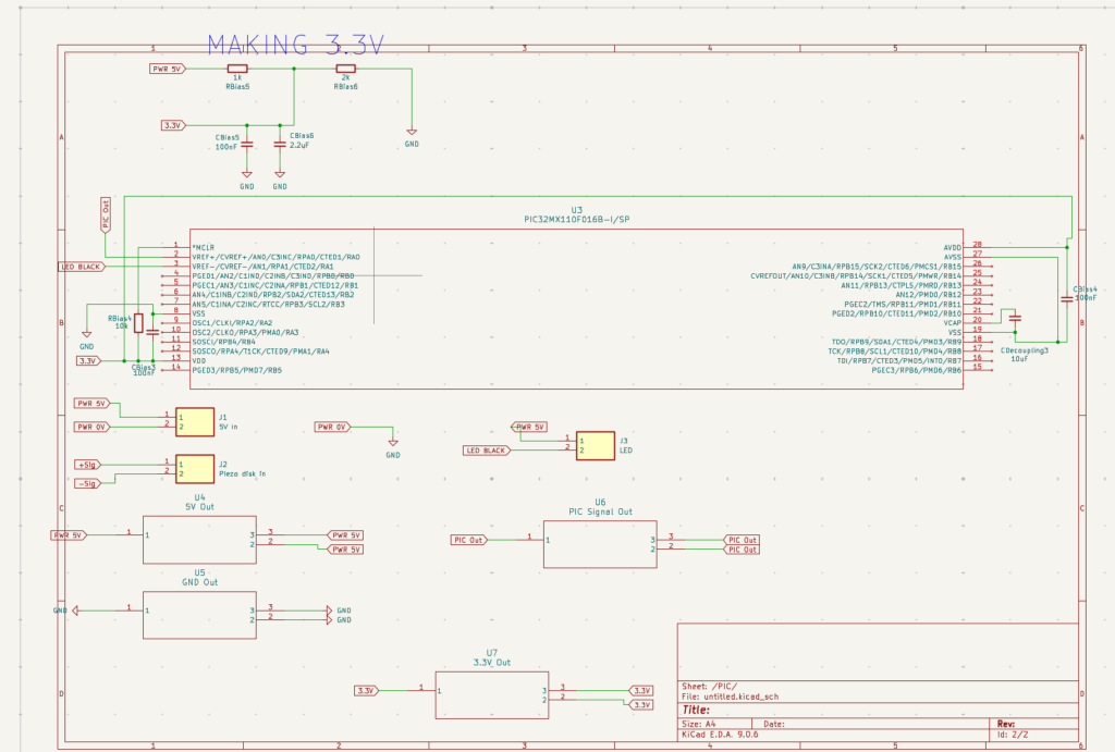
[Fig. 3 – Printed Circuit Board Schematic]
Control Logic & Microcontroller
Purpose
The high output signal of the timer is read by the PIC32 microcontroller, which executes control logic to activate system outputs. Upon detection, the microcontroller generates a 2ms PWM signal to drive a servo motor and activate an LED indicator in testing. The final product features an LED that is activated solely by the timer, such that the LED does not slow down the servo response in real-world applications.
Microcontroller Details
This microcontroller is small and lightweight, which is ideal for the project as not much control logic and thus programming power is needed. While it requires an external module, the Pickit5, to be programmed, it is easily integrated into the circuit design. Because it operates solely on 3.3V at the maximum, a logic level converter must be used to convert its output signal to 5V for the servo, which requires 5V or more to operate.
Programming Process
As the PIC32 microcontroller was available as just a chip, not attached to a circuit board, it must be programmed on a breadboard. With the use of the Pickit5 module that interfaces with the chip, it can be easily programmed with MPLAB like any other PIC microcontroller. The control code for this project is available here. The PIC32 runs a continuous loop of checking for a high signal from the timer, upon which it sends a signal to the servo to move and release the weight.
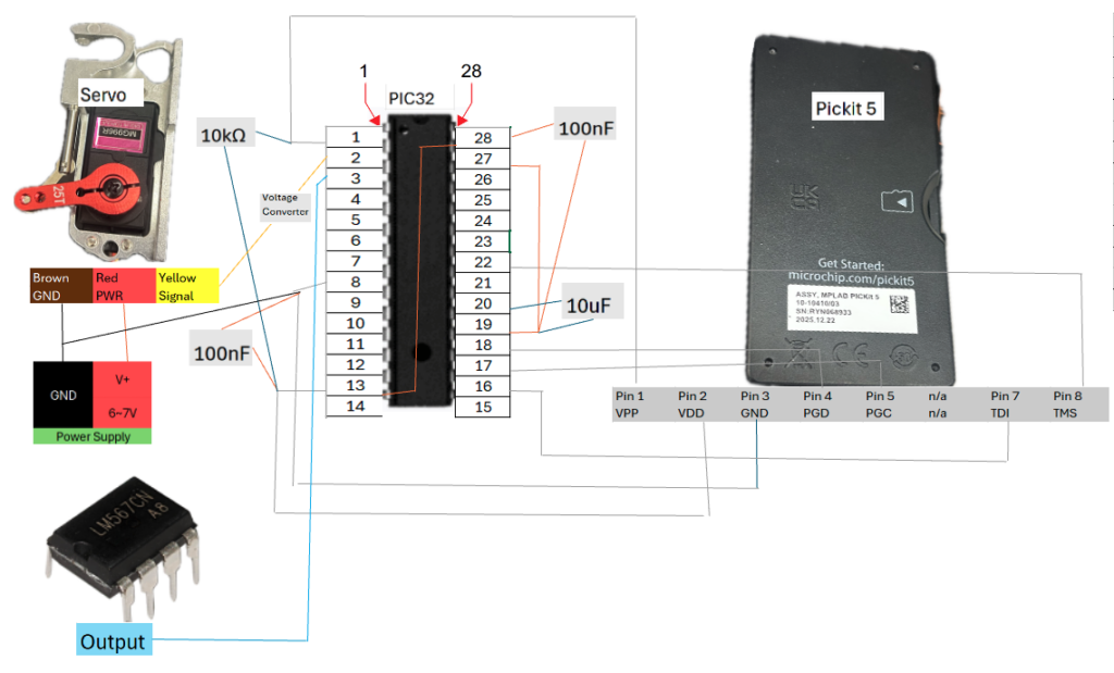
[Fig. 4 – PIC32 programming visualization drawing]
Release Mechanism
A servo-actuated latch mechanism is used to release a payload. When the servo receives a trigger signal from the microcontroller, it rotates 90 degrees, moving a hinged bar that has a weight tied to it. Once released, the weight will be dropped, allowing the remainder of the device to float back to the surface.
Hardware
- Oumefar release servo (PWM controlled)
- Servo arm + latch pin / hook
- Hinged gate + weight
Operation
- Servo holds latch closed, with weight tied to servo arm
- PWM Trigger → rotates ~90°
- Latch releases → gate opens → weight drops
Advantages
- Low power (only active during release)
- Fail-safe after operation
- Simple + compact design
- Waterproof enclosure
- Corrosion resistant parts
Casing
All components are enclosed in a waterproof 3D-printed cylindrical housing. The case was designed in FreeCAD and printed with the help of the Rettner computer lab staff.
Dropsonde-style Case Overview: Aircraft-deployed device for data collection
Integration: Sealed internal chamber protects onboard electronics, External release mechanism enables controlled payload deployment
Design: Cylindrical housing (dry interior, exposed exterior)
Components: main cylinder, endcaps, electronics tray, latch bracket, External latch mounted below housing, actuated via pin
Key Specifications
Inner Diameter: 63 mm
Outer Diameter: 69 mm
Length: 200 mm
Wall Thickness: 3 mm

[Fig. 5 – Casing design]
The electronics are sealed with epoxy glue and waterproof caulk to prevent water damage and cushioned with foam to limit pressure underwater. The servo is waterproof, so it is attached outside the casing with the weight. All wires that must come outside of the casing are securely sealed with the epoxy.
Testing & Results
The system successfully detects a 37.5 kHz acoustic pinger and produces repeatable output pulses corresponding to the beacon transmission, triggering the release mechanism
- Oscilloscope measurements confirm that detection events occurred at approximately 1 second intervals, with pulse durations of about 10 ms. This periodic response matches the expected behavior of standard acoustic pingers and indicates that the system is responding to the intended signal rather than noise.
- The piezoelectric sensor produced an input signal of approximately 11.7 mV, which was amplified using the INA2128 instrumentation amplifier to approximately 0.78 V amplitude (about 1.56 Vpp).
- LM567 tone decoder to reliably lock onto the target frequency and generate clear digital output pulses during detection. The tone decoder output exhibited consistent LOW transitions during valid signal reception, which were successfully picked up by the timer.
- The timer produced a high signal that was long enough to be read by the PIC32 microcontroller.
- The PIC32 sent PWM signals to the servo, which enabled it to move and release the weight.
The system design evolved throughout development to improve performance and reduce cost. Initial testing was conducted using a hydrophone, which provided reliable signal detection but was costly and less practical for deployment. The hydrophone was later replaced by a piezoelectric sensor, significantly reducing cost while maintaining acceptable detection performance. The PCB was redesigned to better fit casing specifications as well.
Cost Breakdown
Piezoelectric transducer (~$1)
INA2128 Dual Instrumentation Amplifier ($24)
LM567CN Tone Decoder ($3)
LMC555 Timer ($3)
MT3608 DC-DC Converter ($8)
BOB12009 Logic Level Converter ($4)
PIC32MX110F016B – I/SP Microcontroller ($3)
Servomotor with Latch ($24)
Metal weight and Steel wire ($4 + $0.25)
3.2V Lithium-ion Batteries ($16)
Battery holders ($2)
PCB – Fiberglass epoxy with copper traces ($11)
PLA casing – 3D printed ($12)
Gorilla Epoxy glue and Caulk seal ($6)
Total Cost: $121.25
This is a great improvement compared to pinger detectors currently available in the market, which typically range from approximately $980 to over $6,400 for high end models. However, the cost could be brought down by optimizing the design even further, which is something to note for future testing.
Limitations
- The piezoelectric sensor exhibited high sensitivity to environmental noise, leading to occasional false triggering in early testing.
- Reliable system operation required a stable 5V power supply, which depended on the voltage converters working perfectly.
- Servo actuation also required proper voltage level shifting and pulse timing to ensure consistent operation. Because of this, the servo was moved to a different power source to prevent it from drawing too much current from the rest of the circuit.
- As the servo operation required much debugging, a final version of the product that could be completely submerged in water was not built. Instead, a version without a release mechanism that could be completely submerged and showed a blinking LED upon pinger detection and a version with only the release mechanism dropped in water were built.
Demonstration
Next Steps & Recommendations
For future adjustments on this project, we propose the following ideas:
- Water-activated, shelf-stable battery – As the product should not be on all the time, it would be ideal for the battery to only activate upon hitting the water. In addition, the battery life should be able to last for at least 40 years, so that the detectors can be stored and used long into the future.
- Biodegradable container and components – As the product will be dropped into the water and left there, all components should be as eco-friendly as possible.
- Larger range – Testing in larger bodies of water would be a next step to ensure that the detector works even if the pinger it must detect is 4,000 meters below the ocean surface.
Thank you!