Abstract
This project aimed to address the issue of limited access to obstetric ultrasound examinations in low- and middle-income countries (LMIC) by reducing or eliminating the necessary training to perform such operations. Sponsored by Professor Benjamin Castaneda from the University of Rochester department of biomedical engineering, the project team worked to develop a low-cost mechanical device which interfaces between the operator and a Butterfly iQ, the portable ultrasound probe of choice. The primarily 3D-printed device features mechanical indicators which inform operators of the correctness of their force application and probe perpendicularity during the operation. All CAD and simulation for this project were performed using Siemens NX, and physical tests were conducted on a maternity mannequin to approximate a pregnant woman’s abdominal geometry. Late into the course of the project, the design philosophy pivoted due to unpromising test results, rendering some of the initial requirements and specifications less, if not inapplicable. Nevertheless, the team communicated closely with the sponsor to ensure that expectations were met amidst constantly changing conditions.
Problem Definition
Prenatal complications are prevalent in low- and middle- income countries (LMICs) since healthcare personnel capable of detecting conditions early by performing ultrasound examinations are rare. Despite existing training initiatives in these areas, retention of these personnel is challenging due to a high rate of rotation in rural communities, as once they are educated on the technology and procedure, they are likely to leave for more developed areas with more competitive roles and enhanced healthcare infrastructure. Transportation back to these rural areas also poses a significant roadblock for visiting healthcare personnel who wish to perform examinations in these communities. The goal of this project is to address the problem by removing the need for training to perform ultrasound examinations. Current processes for delivering point-of care ultrasound (POCUS) in these areas require trained personnel to travel extensively to patients’ homes. By constructing a device which mechanically enforces adherence to the obstetrics Volume Sweep Imaging (VSI) ultrasound protocol, pregnant women can seek ultrasounds from local physicians and healthcare providers who will be enabled to perform these examinations without specialized training.
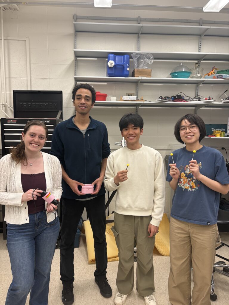
Team Members


Team Sponsor
Professor Benjamin Castaneda
Deliverables, Requirements, and Specifications
Deliverables
| Deliverable | Description |
|---|---|
| 1 | Prototype device that can be tested |
| 2 | Technical report with testing data |
| 3 | Theory of operation manual for device |
| 4 | Website to summarize project work |
| 5 | Poster for design day |
| 6 | Device maintenance manual for technical engineer |
Requirements
| Requirement | Description |
|---|---|
| 1 | The device must be electronically compatible internationally |
| 2 | The device must be easily transportable via plane, boat, and bus |
| 3 | Manual must provide all necessary information for operation, without specialist assistance |
| 4 | The device must be able to be disassembled and reassembled, if applicable |
| 5 | The device must be designed in such a way that it considers the patient during scanning |
| 6 | The device must not interfere with ultrasound functionality |
| 7 | The device must be designed in such a way that it considers the operator during scanning |
| 8 | The device must be designed to accommodate the 95th percentile of patients |
| 9 | The device must hold the ultrasound probe such that the probe is always in full and normal contact with the patient’s abdomen |
| 10 | The gel must not interfere with the function of the device |
| 11 | The device must be compatible with different sizes of ultrasound probes |
Specifications
| Specification | # Value | Units | Description | Method of Evaluation (brief description) |
|---|---|---|---|---|
| 1 | 22 | lbf | Total weight cannot surpass international airline travel restrictions | Measure final product on a scale |
| 2 | 22x14x9 | inch | Total system’s size when disassembled must fit within a carry-on bag based on airline travel restriction | Measure product with a tape measure |
| 3 | 1.00E+02 | Wh | Maximum power contained in each Lipo battery used to run the system, if applicable, must be less than 100Wh to comply with airline travel restrictions | Verify with the battery’s specification data |
| 4 | 18 | min | The system maintains a constant scanning time of 18+/-5 min | Record the time each scan takes with a timer |
| 5 | 6.7 | lbf | The maximum force the system applies across a cross-sectional area of 3.08 in^2 (probe area) is 6.7 lbf. | Verify with a force sensor |
| 6 | 25 | Wh | Each scan must use no more than 25 Wh. | Perform scans on multiple patients |
Concept Development & Analysis
Initial Concepts
Concept 1 uses an adjustable harness-type strap to secure the device to the patient and leave the stomach area open for scanning. The ultrasound probe rides along an elastic rail spanning the scanning area and attached at either end to the top, bottom, and sides of the frame to ensure the accuracy of the sweep trajectory without expert knowledge. Design 2 is a variation of design 1 and uses an elevated rail above the patient’s stomach to avoid interaction with the gel on the patient. The ultrasound probe sits in a carriage on rollers that allows for constant perpendicularity. The elevated rail is interchangeable so that the user can choose from a range of varied sizes depending on patient geometry. Similar to the first two designs, concept 3 is a patient-mounted device with two telescoping poles sitting along the sides of the patient to change the locations of the top and bottom semi-rigid rails in the shape of an arch. An elastic middle rail is attached to the top and bottom rails with clamps and can be moved horizontally with the probe fixture clamped in one location to allow for horizontal sweeps. For the vertical sweeps, the middle rail can be clamped on the top and bottom rails so the probe fixture can be moved vertically along the rail. Lastly, design 4 is also mounted on the patient. On the side panels, there is a slider mechanism acting as a mounting point for the scanning frame to move vertically across the patient’s abdomen to switch scanning positions. The scanning rail is secured to the slider using screw fixture and is a four-bar mechanism. Since the rail is not curved but rather a trapezoid, a joint must be implemented within the fixture to allow the probe to rotate within a certain range to always ensure normal contact with the abdomen.
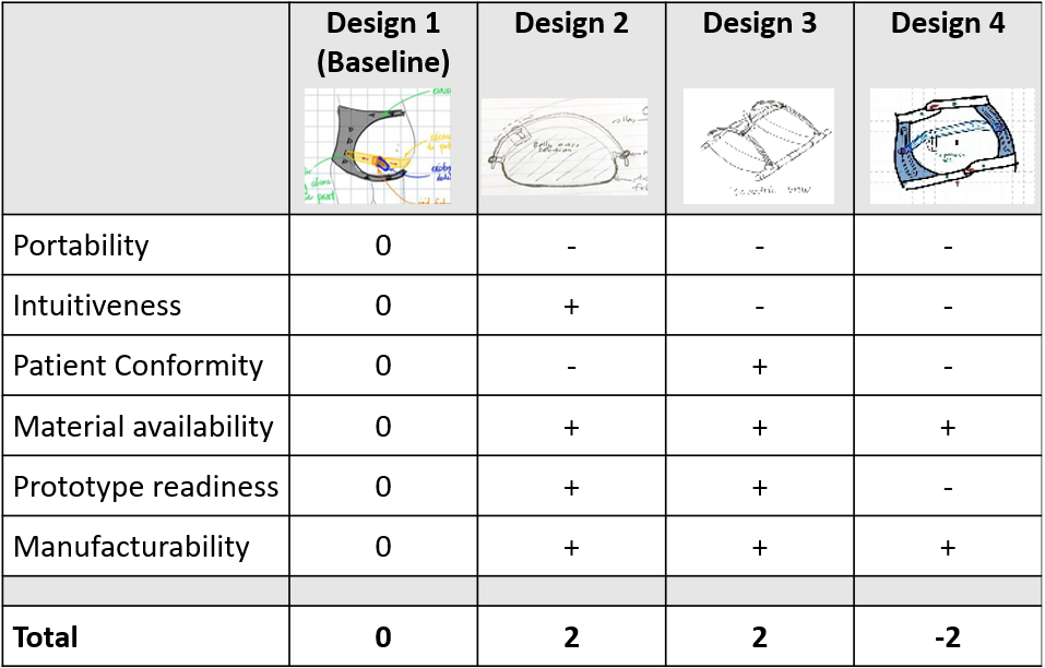
Although design 2 and design 3 were tied in the Pugh matrix, the team decided to move forward with the main functionality components of design 3 being built into the framework of design 1. The top and bottom rails of design 3 were built into the fabric above and below the stomach of design 1. The probe fixture used a detent mechanism to allow for changing the orientation based on the sweep. The rails contained a pulley system to allow for consistent traversal of the middle rail along the top and bottom rails for the horizontal sweeps. Vertical bars were added to the sides of the fabric to outline the stomach and help prevent the top and bottom rails from being pulled inward with probe movement.
Initial Chosen Design
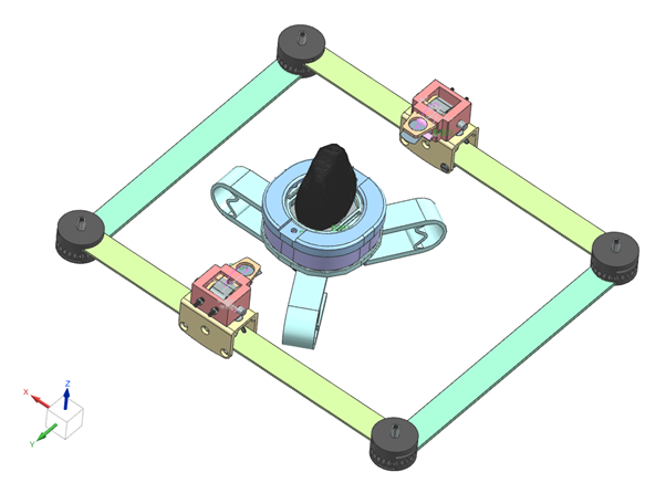
The initial design philosophy was to create a device that properly performs the ultrasound operation mechanically. Several key design targets for this design were portability, standalone functionality, multi-axis motion capability, force application, and adaptability to patient geometry. The design was broken up into four subsystems. First, the constant force spring system maintains vertical pass trajectory and applies the downward force. The constant force springs were attached to the second subsystem: the 3D printed probe mount, which enables the preset 90 degree rotation of the probe using a detent mechanism to switch between vertical and horizontal passes. The constant force springs were mounted on 3D printed carriages part of the third subsystem, the parallel pulley and rails, which maintain parallel horizontal motion. Finally, the elastic harness system attaches to the rails on the frame and adjusts the fit to patient geometry and contributes to force application.
Initial testing revealed several shortcomings with the design. First, the constant force spring system was trying to accomplish the perpendicularity, force, and trajectory goals, but by trying to do all three, it was failing at each. The pulley system also did not provide the smoothest motion and the team was not able to make the frame more comfortable. The overall system was slightly bulky as well. Thus, the team decided to pivot.
Final Design
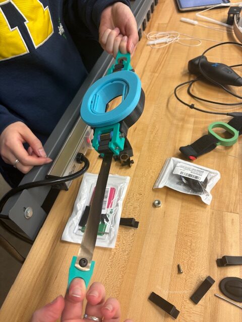
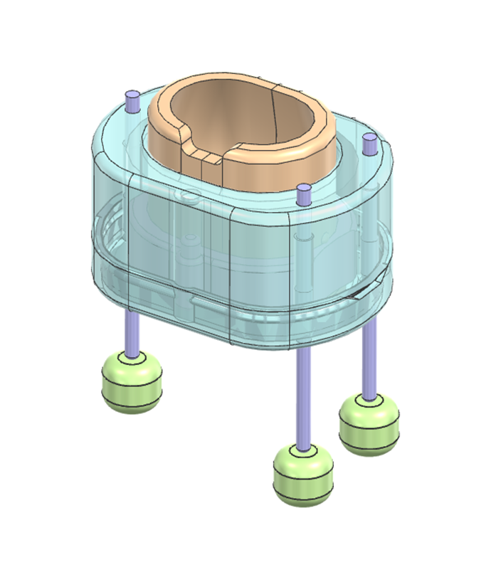
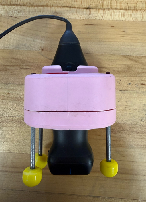
After initial testing demonstrated the difficulty of pulling the middle rail with the pulley system using the probe and mount, the team decided to pivot treating the design as a training device. The frame and rail system were removed, and the mounting fixture was changed to be a standalone device. While the portability, standalone functionality, force application, and adaptibility to patient geometry design targets were kept, the multi axis motion capability was swapped for normal contact of the probe on the scanning area. The design has a spring-loaded force indicator made of inner sleeves with kinematic mounting to accomodate many probe sizes. The user holds and applies a force on the outer hollow piece which transmits a greater force on the inner sleeves and probe as it moves down further.Color bars correlating displacement to force indicate to the user if they are in the acceptable range for the scan. There is also a spring-loaded perpendicularity mechanism made of three rods for the three points of contact to ensure perpendicularity on local scanning areas. Matching colors on top of the rods indicate to the user if they are maintaining normal contact.
Analysis
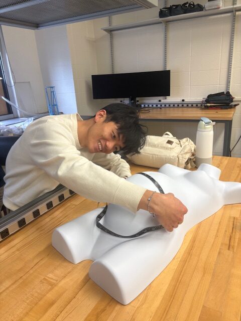
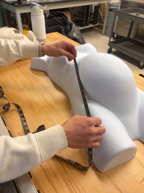
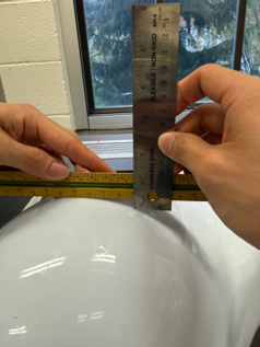
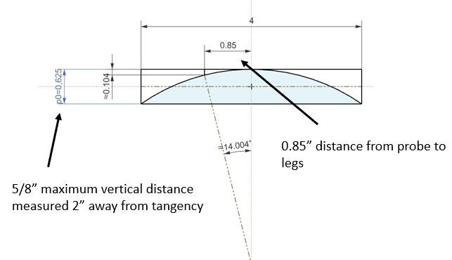
Once the team decided to pivot designs, curvature analysis was performed to determine how many “legs” were needed to provide perpendicularity indication. Measurements were taken as shown in Image 4 and used to create an NX sketch as seen in Image 5. The maximum error with the 2 leg configuration was roughly 14 degrees while the maximum allowable error is 10 degrees. Thus 2 legs on one side was not sufficient for the perpendicularity indication and another one was added to the other side.
Material Choice & Manufacturing
Material Choice
The main material used for this prototype was PLA, as it is a low-cost ($25/kg) and accessible choice. In the initial design, PETG was also used in 3D printing the probe mount due to the presence of a detent mechanism that allowed the probe to rotate and lock into two positions. In the final version of the design, the use of PETG was omitted because the probe mount no longer required the detent mechanism. PLA was used in printing the force-indicator component of the probe mount due to its relative durability, since this part houses two springs and supports the weight of the probe, and is subjected to repetitive compressing forces. For the perpendicularity indicator component of the probe mount, a 0.185-in steel rod was used to make the long rods and 0.25-in aluminum rods were used to create 0.5-in sleeves.
Manufacturing
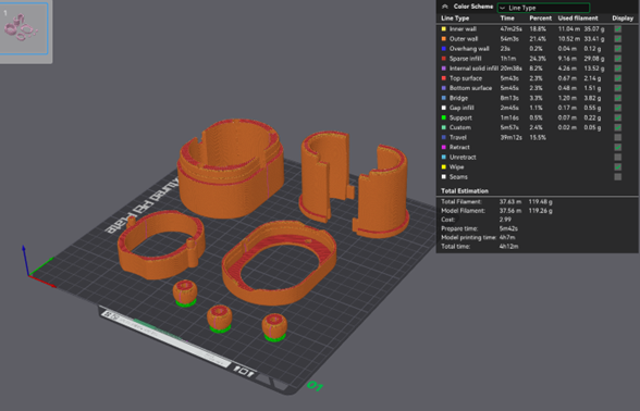
The main manufacturing method used for this prototype was additive manufacturing (FDM 3D printing), which allowed for rapid prototypes and design iteration. The entire model can be printed in under 5 hours on one printbed. Additive manufacturing is also a low cost solution, with each device consuming ~$4 of material. The open source nature of 3D printing also appropriately addresses the accessibility mission. Files can be shared publicly online and distributed locally with 3D printer access. It also opens the door to community-driven design improvements. In addition to 3D printing, the metal rods were machined to get to the correct length and diameter. Since these rods must slide smoothly within the probe mount, machining them out of metal can prevent the issue of layer lines from 3D printing parts rubbing against each other, causing rough movement, and potentially jamming the parts. They were then press-fit together to create the single pieces.
Project Results
Final Device Prototype
Overall, the final design and prototype is best used as an indicator to users of whether they have enough force and are at a normal angle with the stomach. It successfully met all the project requirements and 3 out of 4 specifications. Initial requirements and specifications included a few electrical components which are no longer applicable since the device is fully mechanical. Additionally, since it is mostly 3D printed, the design can be open sourced for easy replication and reproducibility.
Testing
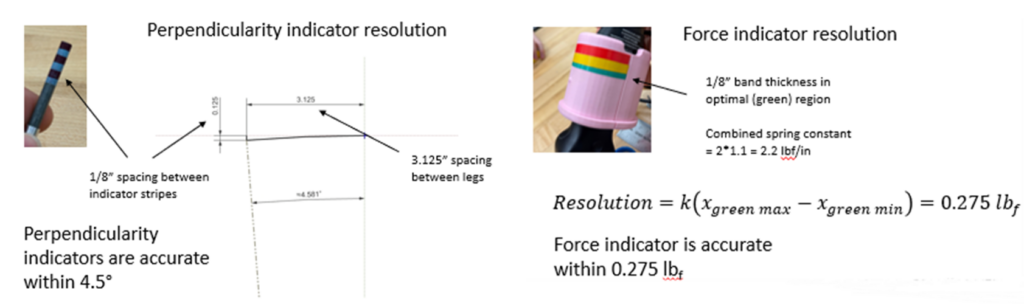
In addition to testing the device on a pregnant phantom model, the team also calculated the resolution of the perpendicularity and force indicators to determine accuracy of the device. As seen in Image 8, the perpendicularity indicators can show accuracy of the normal angle withing 4.5 degrees while the force indicator is accurate withing 0.275 lbf.
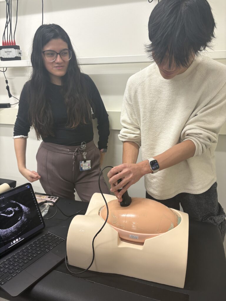
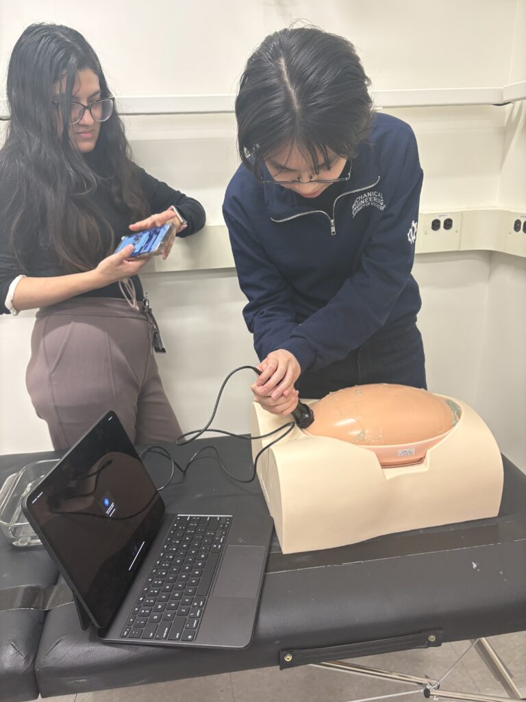
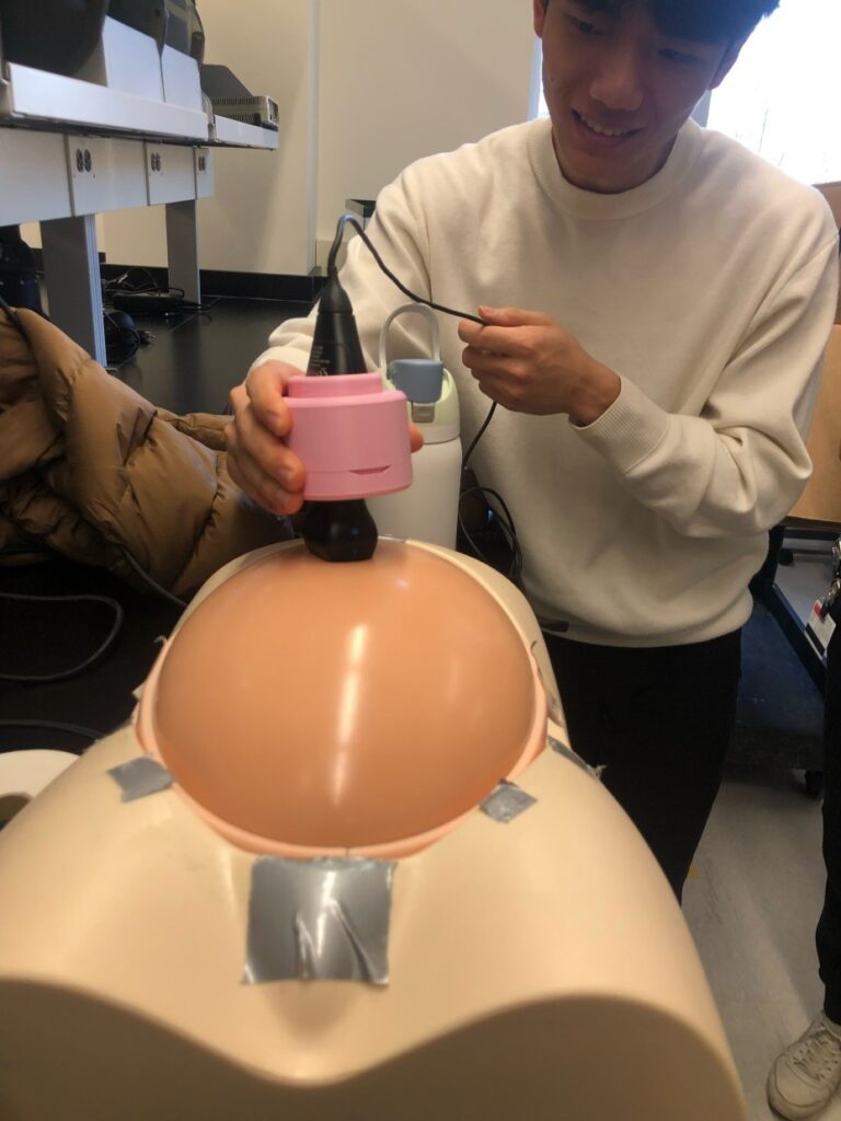
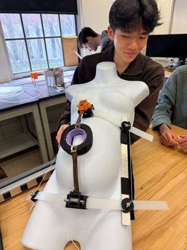
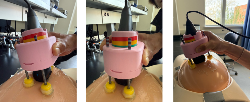
The team tested the final device on a pregnancy phantom in Professor Castaneda’s lab. The left image below shows the device indicating that not enough force is being applied on the probe holder and that the probe is not in normal contact with the stomach. The middle image demonstrates the probe being pressed with enough force (at the green bar) and being at a perpendicular angle with the stomach (same levels on the perpendicularity indicator legs). Finally, the right image tests the functionality of the device on vertical sweeps.
Future Work
In terms of manufacturing, future work could include shifting more to fully 3D printed pieces and buying off-the-shelf (OTS) parts. Due to the time constraints with the late design pivot, manual machining was chosen which was the largest contributor to system cost. In terms of design, further iterations could implement the constant scanning time or speed specifications. The system could be automated using electronic sensors and robotics and the trajectory could be marked with light or laser lines. Lastly, future work would also include conducting more testing to evaluate if new learners perform the VSI protocol better with or without the device.
Additional Documentation
Final Design Report
Final Design Presentation
Final Design Poster
Presentation Video
Acknowledgements
The team would like to acknowledge and thank our sponsor Professor Benjamin Castaneda from the UR BME department. Additionally, the team would like to thank our TA, Elizabeth Martin, and Professor Muir for their help, guidance, and support throughout the project. Lastly, the team would like to thank Sam Kriegsman, Jim Alkins, Chris Pratt, and Kaleb Chitaphong for assisting with 3D printing, manufacturing, and ordering.
Pictures