Project Background

Research on the loss of support in sports bras over time is minimal, especially when compared to other workout equipment like shoes, compressive sleeves, straps, etc. The loss of support in sports bras affects the comfort and performance of female athletes around the world and increases the chances of experiencing breast tissue or pectoral muscle injury. With no clear guidelines on how to reduce the loss of support in sports bras, this apparatus will aid research to move towards filling this gap in knowledge.
Customer Specifications
| Priority | Needs | Metric (with units) | Goal |
| High | Multi-Directional Loading | # of directions force is applied | 3 directions (X,Y,Z) |
| High | Cyclic Loading | Duration(s) Repeats | 10 s – 15 s 50 repeats |
| Medium | Size Adjustability | # of sports bra sizes that can be tested | 5: XS, S, M, L, XL |
| Low | Agreement with Preliminary Data | Change in force required to reach repeated angle (N) | ↓ in force (N) |
| Priority | Wants | Metric (with units) | Goal |
| Medium | User-Friendly | Training time (min) Setup time (mins) | < 60 mins < 10 mins |
| Low | Portability | Weight (kg) Dimensions (cm) | < 45 kg < 120 cm x 120 cm |
| Low | Type Adjustability | # of types of sports bras that can be tested | 4: racerback, traditional (2-strap), cross-backs, multi-straps |
Initial Approach
An initial survey was sent to female student-athletes on campus to ask about their sports bra use. We asked questions such as how often they wore sports bras, what style they typically wore, and, most importantly, to describe the motions that it took them to put on and take off their sports bra. This was the fundamental guiding point in our design. The results of our survey showed that the “triangular motion” was the most common way to put on a sports bra.
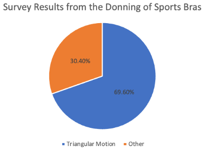
Pie chart generated from survey data showing the popularity of the triangular motion when female student-athletes at the University of Rochester put on their sports bras
From this, we performed motion capture analysis, where we could break down the motion and create verbiage that would describe each step of the process (insertion, grab, triangular lift, and spread). Along with this, we were able to determine the angle at which the sports bra needed to be lifted to ensure an accurate representation.
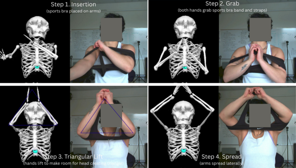
Description of motion verbiage with video camera footage and reconstructed skeleton footage from marker-less motion capture
Our initial approach guided the rest of our design process, and from here we could begin brainstorming and prototyping.
Prototyping Process
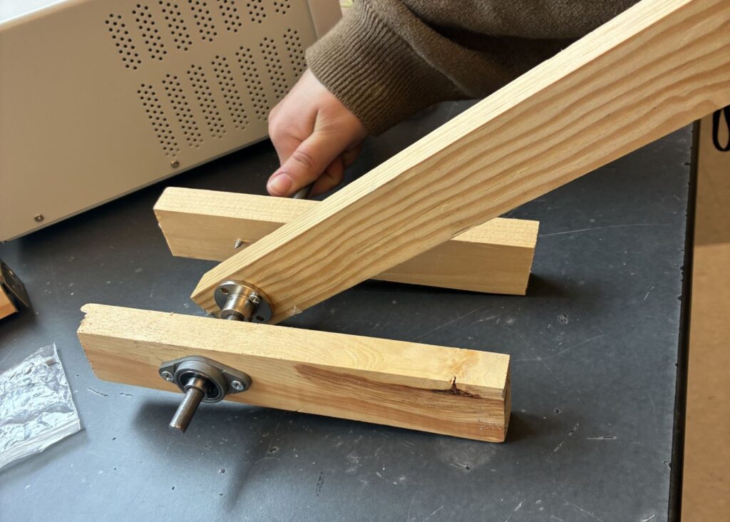
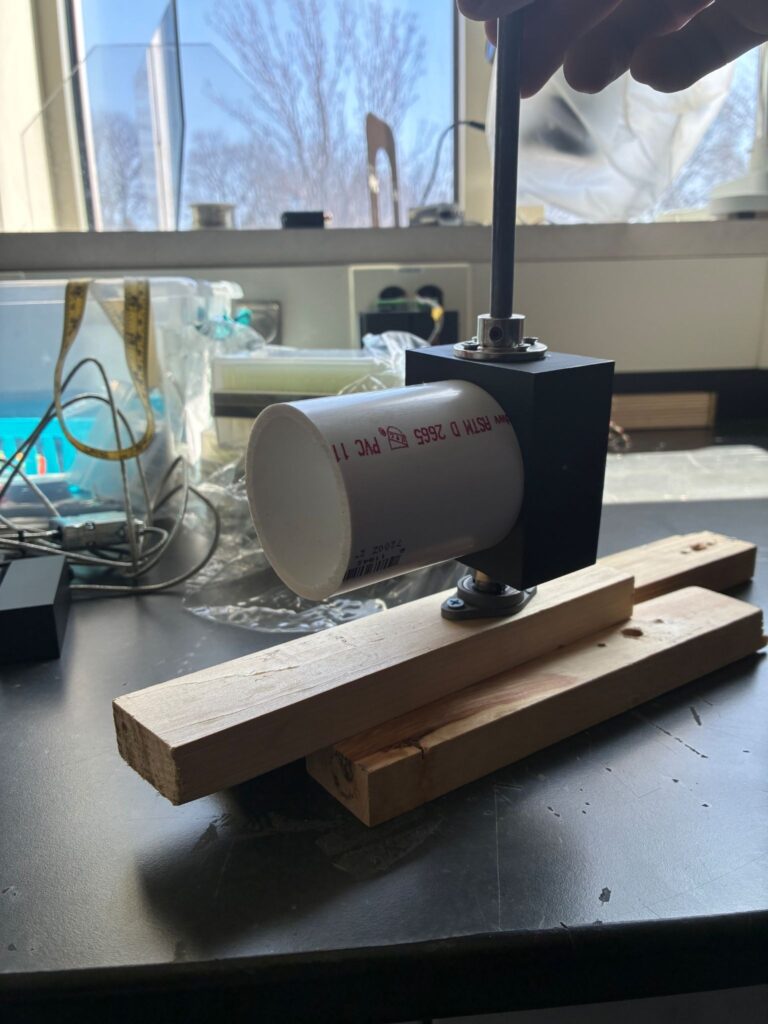
Once a suitable design was selected for our application, we moved on to the prototyping phase. Prototypes were created for the back lever arm (1), the side arms (2), and the load cell (3). Each prototype was considered successful.
Materials used:
- Wood
- Flange couplers
- Pillow bearings
- Steel rods
- PVC pipes
- 3D printed part
Final Design
1- Insertion
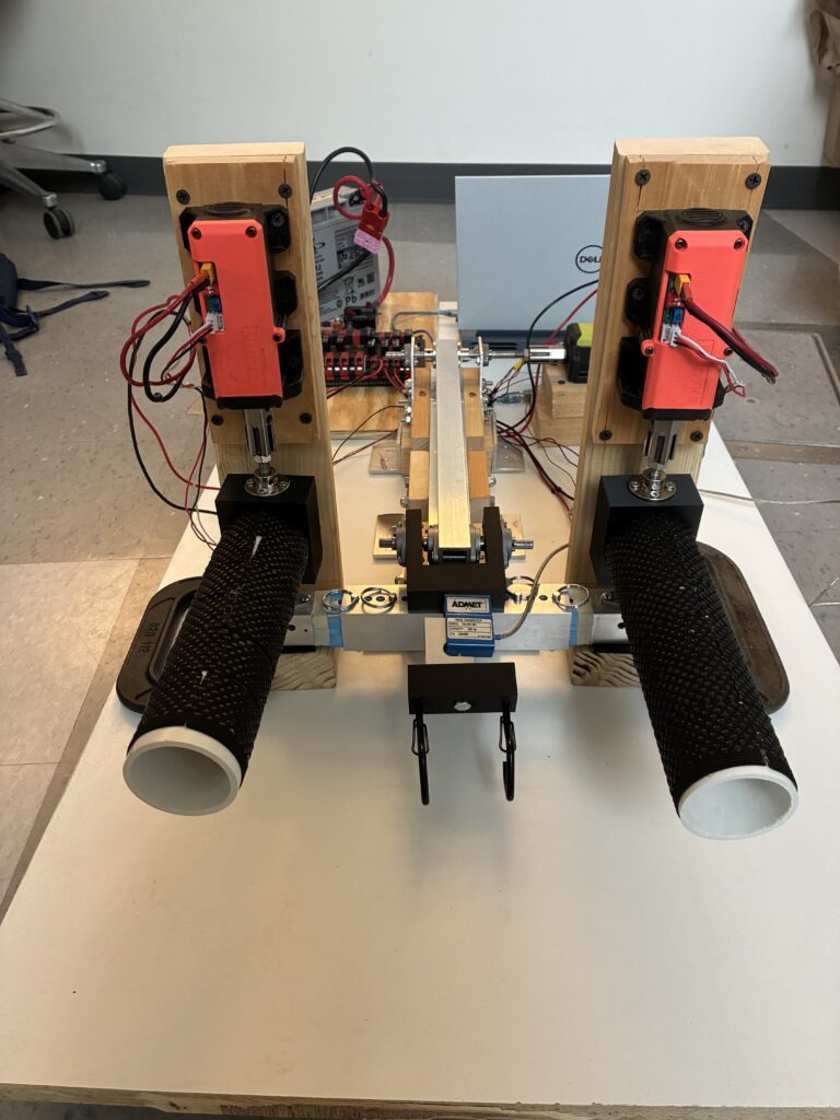
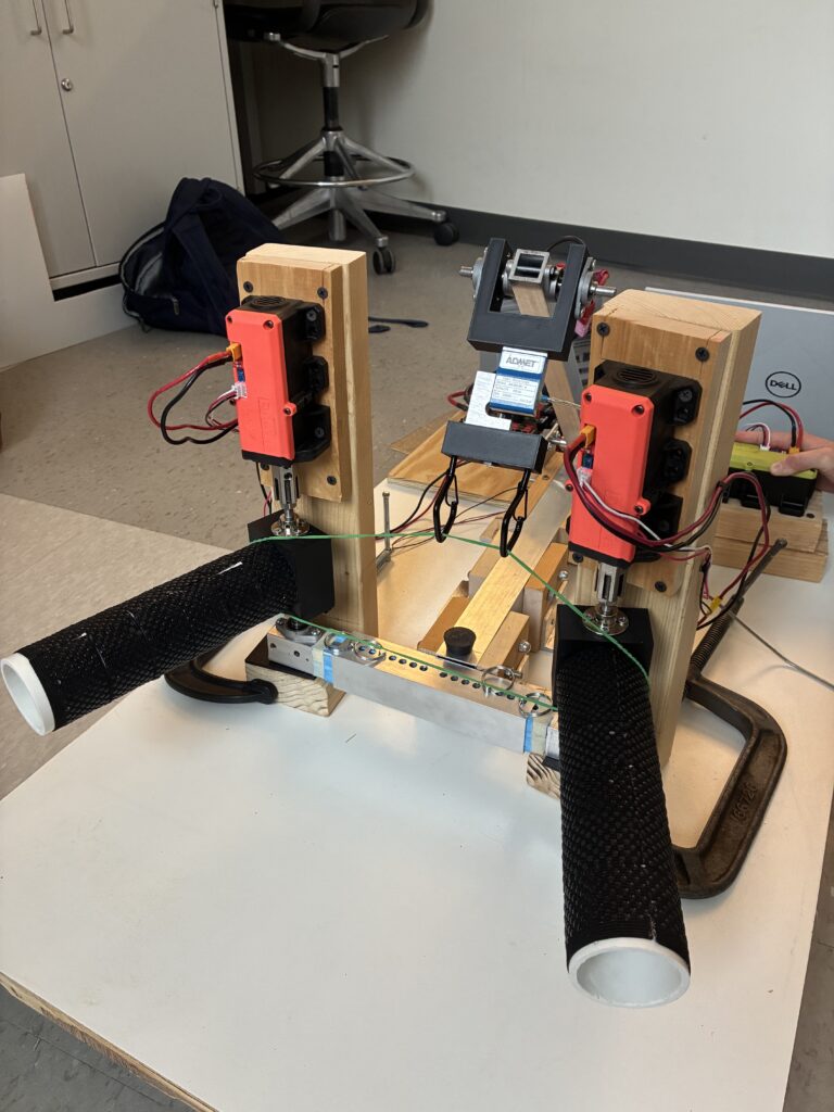
The sports bra is placed onto two side arms attached to a manually adjustable base.
2- Grab
Hooks positioned at the end of the lever arm are clipped to the band of the bra.
3- Triangular Lift
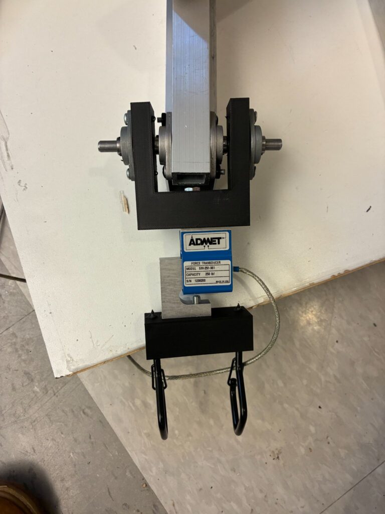
The lever arm pulls the bra upward at an angle while an integrated load cell measures the resulting force.
4- Spread
Two side arms rotate outward at an angle, simulating the lateral stretching to fit the garment over the head.
Customer Use Scenario
The customer use scenario for Dr. Buckley and Dr. Rizzone begins in the Buckley Lab, where the sports bra’s baseline material properties are first established through axial tensile testing. Following this initial assessment, the apparatus is manually adjusted to the garment’s specific dimensions, and the bra is placed onto the device. To initiate testing, the user connects a laptop to the Arduino Uno via USB, activates the power supply, and launches a custom MATLAB interface. This application allows the user to input critical parameters, including the side arm and lever arm angles as well as the total repetitions.
Once the protocol is executed, the apparatus performs the specified repetitions, with a load cell at the end of the lever arm capturing the precise force required to reach each angular displacement. Upon completion, the device returns to its resting position for removal, after which the sports bra undergoes a final round of axial testing to quantify any post-cyclic deformation. By correlating the force trends captured during operation with the changes in material properties, this system provides the Buckley Lab with high-fidelity data essential for advancing sports bra research and performance analysis.
“What if the apparatus is not working?”
- Are the red lights on all three motors on?
- No red light = No power
- Check power cables, motor controller, and battery connections
- Constant red light = Power on and signal connection
- This is what you want!
- NOTE: Sometimes when power is turned on and no command has been given yet, flashing occurs (typically slow flashing to represent no signal connection)
- Very slow flashing (>2s) = Power on but NO signal connection
- Check signal cables and Arduino connections
- Make sure user interface and/or code is not giving errors
- Slow flashing (2s) = Temperature protection
- Turn off power immediately
- Double check voltage to motors is under the maximum of 24V
- NOTE: The base is wood, so you need to be extra careful with high temperature warnings
- Fast flashing (0.3s) = Jam protection
- Ensure torque experienced by the motors is under the listed maximums
- Max torques are 55Nm for S550 (green motor) and 35Nm for S350 (red motors)
- Rated torques are 18Nm for S550 and 15Nm for S350
- If under the maximum torques, contact DOCYKE to help determine issue
- Very fast flashing (0.1s) = Over current protection
- Turn off power
- Ensure current is under the 25A maximum for each motor
- If under, contact DOCYKE to determine issue
- No red light = No power
- Are all three motors showing a constant red light and working as expected, but no motion is occurring?
- This is likely a set screw loosening issue
- Set screws on each flange coupler to rigidly attach rods at hinges should be tightened and possibly re-glued (can use LOCKTITE)
Limitations
The high current demand of the motors used in the apparatus was a major limitation. Each motor requires 25 A, which exceeded the capabilities of a bench-top power supply, so we had to resort to using a battery-operated system to meet the power requirements.
Our small group of 3 people and our limited budget of $150 per person led to a financial limitation that influenced the material selection and the component quality. We completed all of the machining ourselves. With a larger budget, more advanced components could be utilized to improve the durability of the apparatus.
This project was also constrained by a limited timeline, which required us to quickly plan and rapidly go through design iterations. The time restrictions limited the extent of optimization and additional testing that could be performed on the final apparatus.
Next Steps and Future Directions
When given to customers, along with BOM and SOP, we plan to also describe how to replace motors.
- Other motors -> User interface and wiring may need to be reconsidered and altered
- Purchase of new motors with stall torque -> 20 Nm
- If necessary, purchase shaft coupler to attach to 8 mm rods
- Ensure motors are aligned with rod properly when attached
- Servo motors -> User interface and wiring remain the same
Acknowledgements
We would like to acknowledge our supervisor, Dr. Regine Choe; our project management liaison, Elizabeth Martin; our instructors, Dr. Seidman and Dr. Castañeda; our available senior research engineer, Mr. Martin Gira; the Rettner shop manager, Mr. Jim Alkins; and our customers, Dr. Mark Buckley and Dr. Katherine Rizzone, along with Jeff Sciortino, the X-Cats Robotics team.