Team Members: Jared Lipkin, William Seastrand, Ajay Sujaritha Ganesh
Advisors: Michael Heilemann, Dan Phinney
What is it and why is it important?
Preamplifiers are the foundational link in any audio signal chain. Whether recording a voice memo, or tracking a record in a professional studio, the preamplifier is vital in bringing your sound to the next level (line level that is).
The analog signal generated from any microphone is quiet, weak, and susceptible to noise interference. For this reason, any recorded signal from a microphone needs to be brought up to line level, at which point it is strong high fidelity audio.
Mic Level: The voltage strength of an analog audio signal, directly out of a microphone and through XLR cables. This is typically around 1 – 10mV.
Line Level: The voltage strength of the input signal post-preamplifier, used to send audio between components before it is through a power amplifier to drive speakers. This is typically around 1 – 2V.

Project Goal and Objectives
- Design and fabricate a low-noise, 2-channel microphone preamplifier for a local Grammy-Winning audio engineer, Ignacio “Nacho” Molino, by utilizing vacuum tubes and/or discrete transistors and/or operational amplifiers.
- Allow for it to interface with dynamic and condenser microphones, using standard XLR connectors, and mounted in a standard mixing console or rack.
- Achieve less than -90dBu of noise at unity gain
- Achieve less than 0.1dB variance in frequency response between 10Hz and 20kHz.
- Meet with the customer regularly to receive feedback and provide updates on the state of our product throughout the year.
Individual Design Approaches
We each took on three main component-based approaches to preamp design listed below, in an initial attempt to finalize a direction for our design.
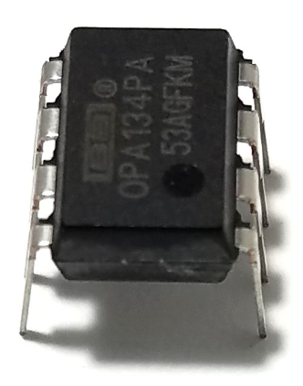
- Operational Amplifiers: Tiny black box/chip containing two inputs, in which the voltage difference between both are amplified.
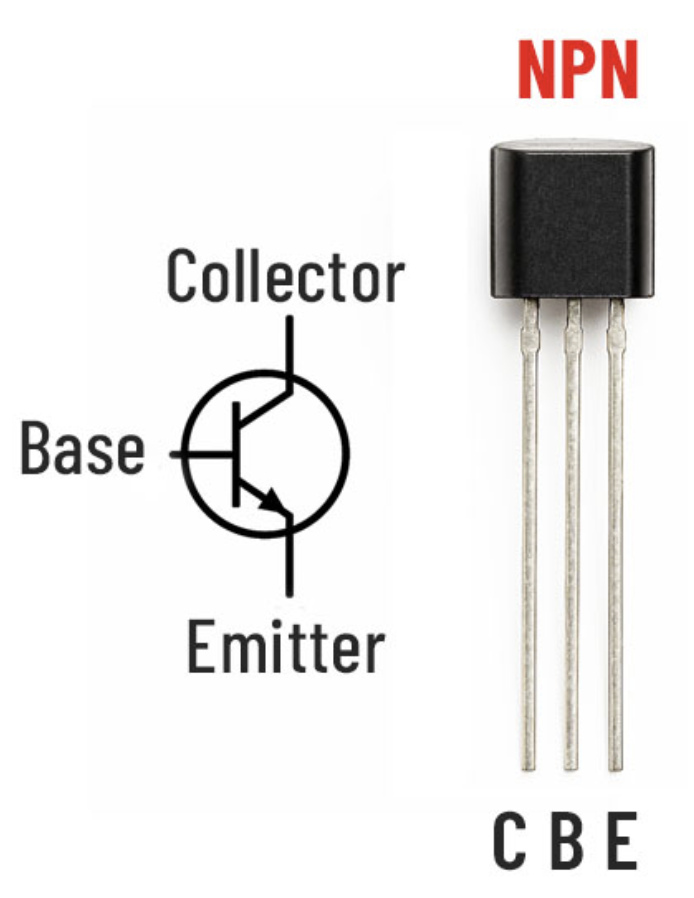
- Transistors: Switch based amplifier that turns on a large electric current to amplify an input signal.
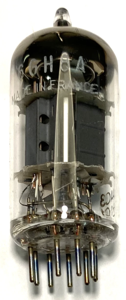
- Tubes: Bulb shaped devices that act as voltage controlled valves, passing through and amplifying small electrical signals.
Conclusion Op-amps possess little controllability, while the over-saturation of tubes strayed away from our customer’s desired functionality of our product. Therefore, we committed to a transistor based approach, as it would provide clean output and involve maximum control over the design process.
Initial Survey of Preamplifiers
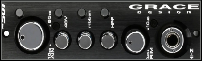
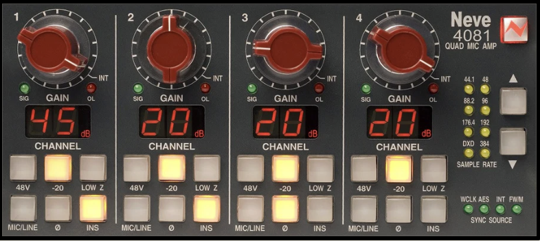
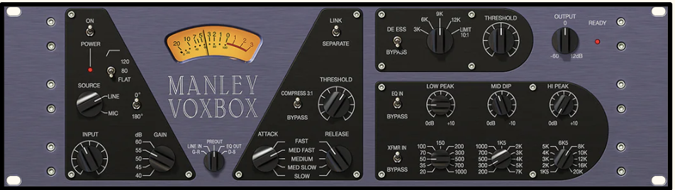
Before our initial design, three preamplifiers in Gavett Studio, with distinct selling points and known design elements similar to our customer’s go-to’s, were tested to determine how circuitry affects sonic quality, what makes a popular preamplifier successful, and the final direction of our design.
Blind Mix Test
We decided to record a cover of “More Than a Feeling”, a rock tune in Nacho’s wheelhouse of mixing catalogue. In Gavett Studio on the University of Rochester’s campus, we recorded guitar, bass, drums, and vocals going into each of the above preamps simultaneously. After sending an unlabeled mix to Nacho, he correctly identified the microphone and preamplifier 82% of the time. This outcome proved that preamplifier design is not arbitrary, and confirmed our design intent of a clean sounding preamp with the option to drive the signal.
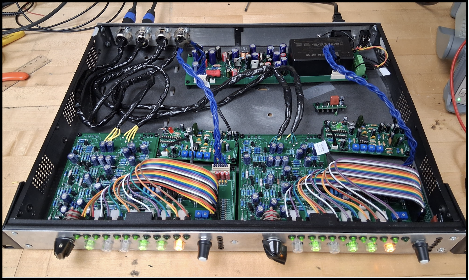
Subsystem Design
Power Supply Circuit
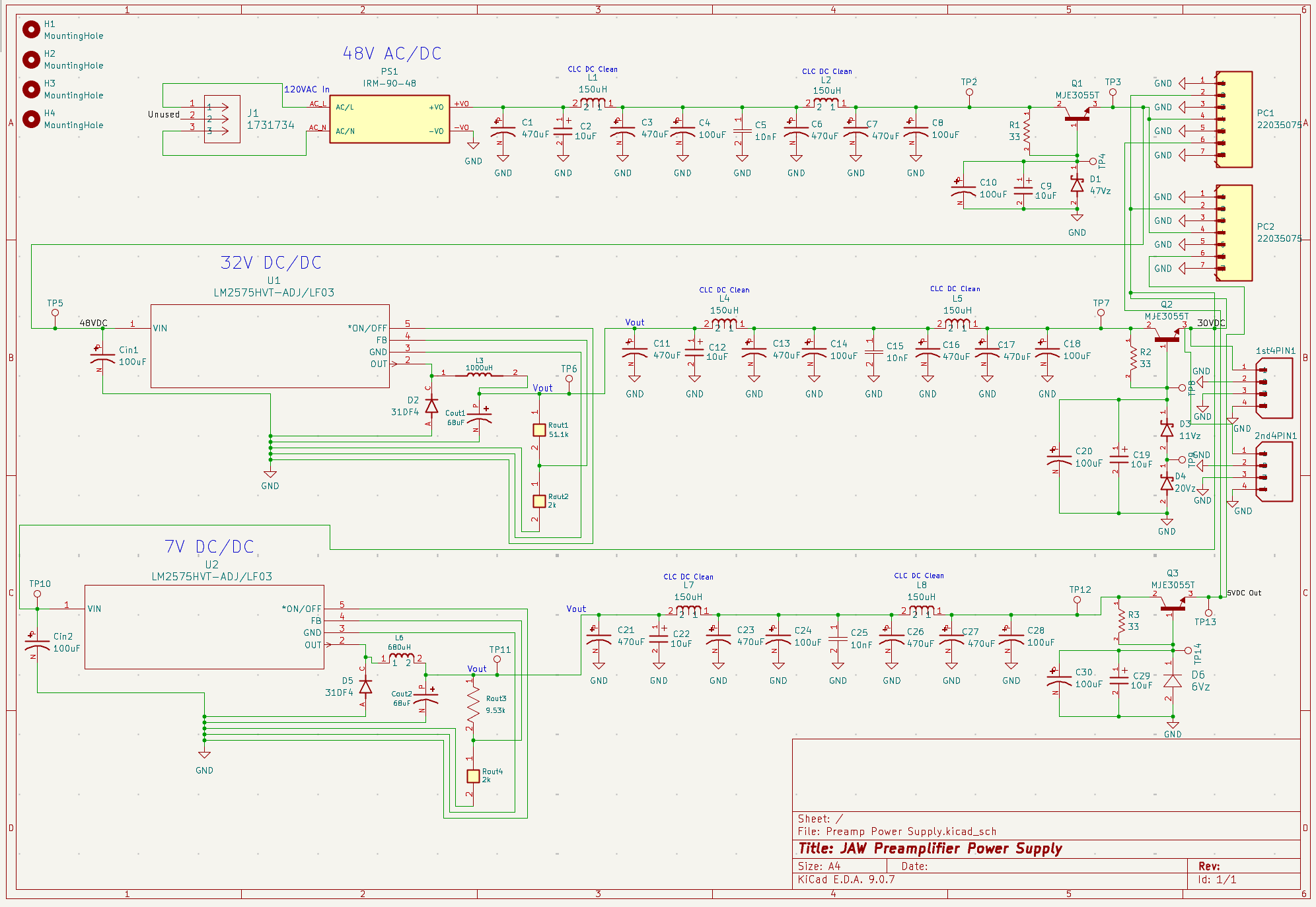
In order for any device to function, a power supply is necessary to transform power from any outlet into clean usable voltage, specific to the device’s needs.
- Our device requires three separate voltages including 46VDC, 30VDC, and 5VDC to power the gain stages and phantom power, drive circuit and high pass filter, and LEDs, respectively.
- Switching devices were implemented for each power stage, to achieve high efficiency and noise reduction. A switching converter steps 120VAC to 46VDC, followed by switching regulators that derive the 30V and 5V rails.
- Capacitor + Inductor + series pass transistor circuit networks were implemented between stages to reduce ripple voltage to less than 1mV, providing clean stable power for the various features of our preamplifier.
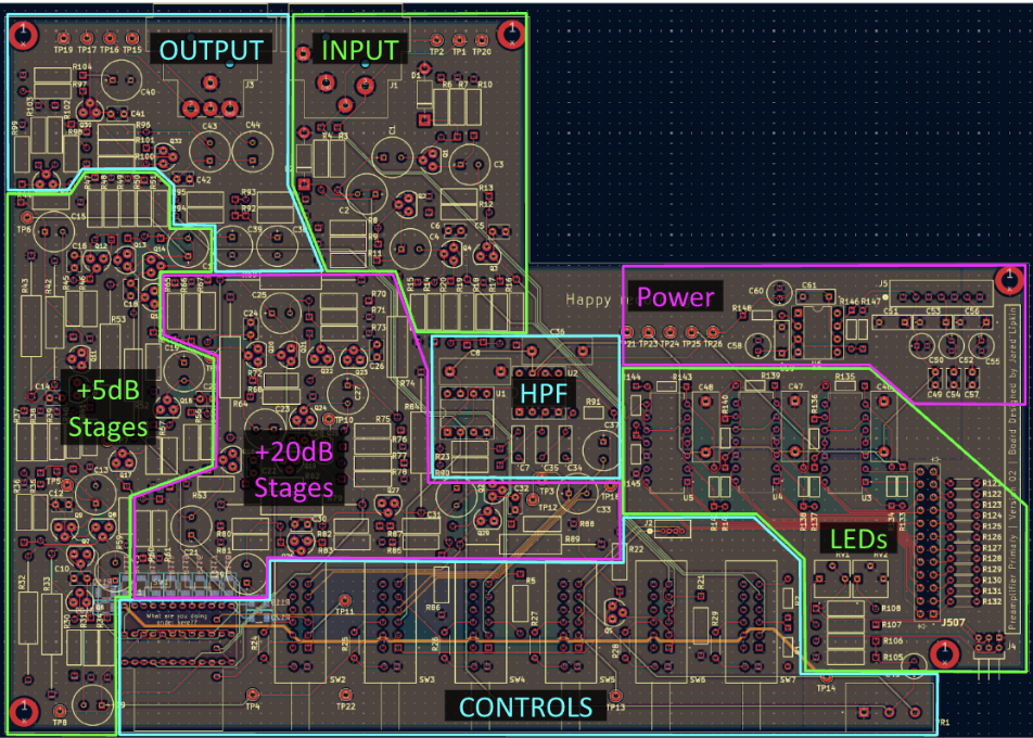
Main Preamplifier Circuit
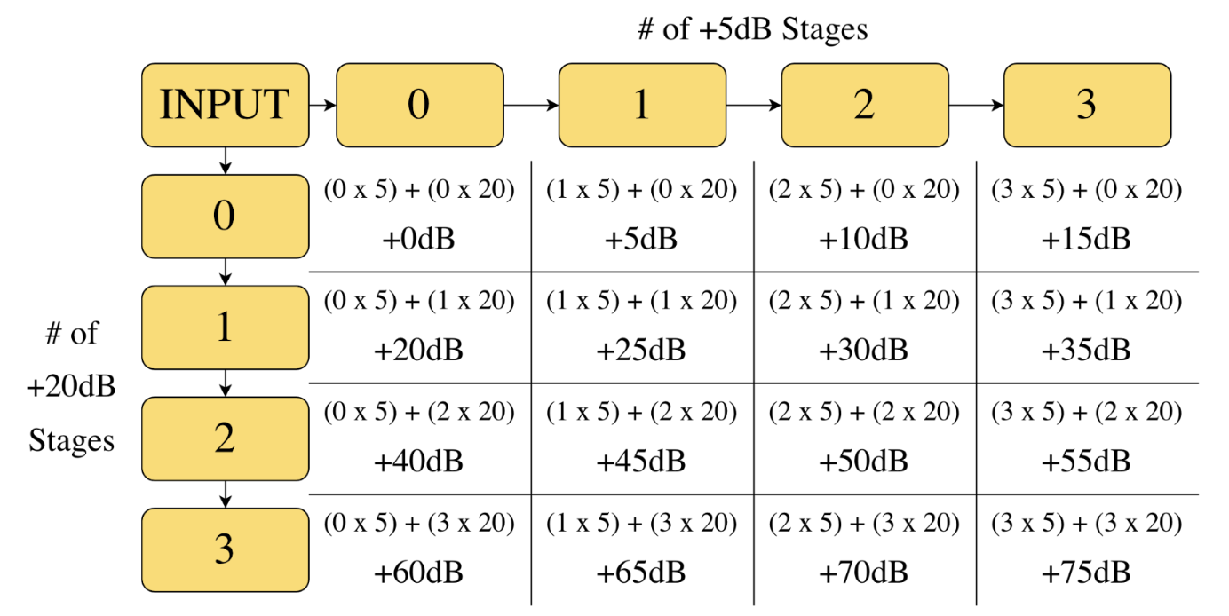
Now for the primary purpose of this device, the main amplification boards utilize 5dB and 20dB transistor based gain stages. The stages cascade in a stepped gain format from the user’s perspective, ranging from +0 to +75dB. This allowed for the easiest development process and minimizing component count while still allowing for complete flexibility.
Outside of the main amplification circuitry, a 3rd order high pass filter was implemented in order to reduce any incoming noise below 75Hz significantly for a clean and minimally noisy signal.
LEDs are implemented at the output for visual confirmation of controls in addition to aesthetics.
User Interface
The front panel layout for this design was determined by personal aesthetic taste, customer request, and PCB layout considerations. It includes an output level meter on each channel, which serves as a reference when dialing in optimal gain levels.

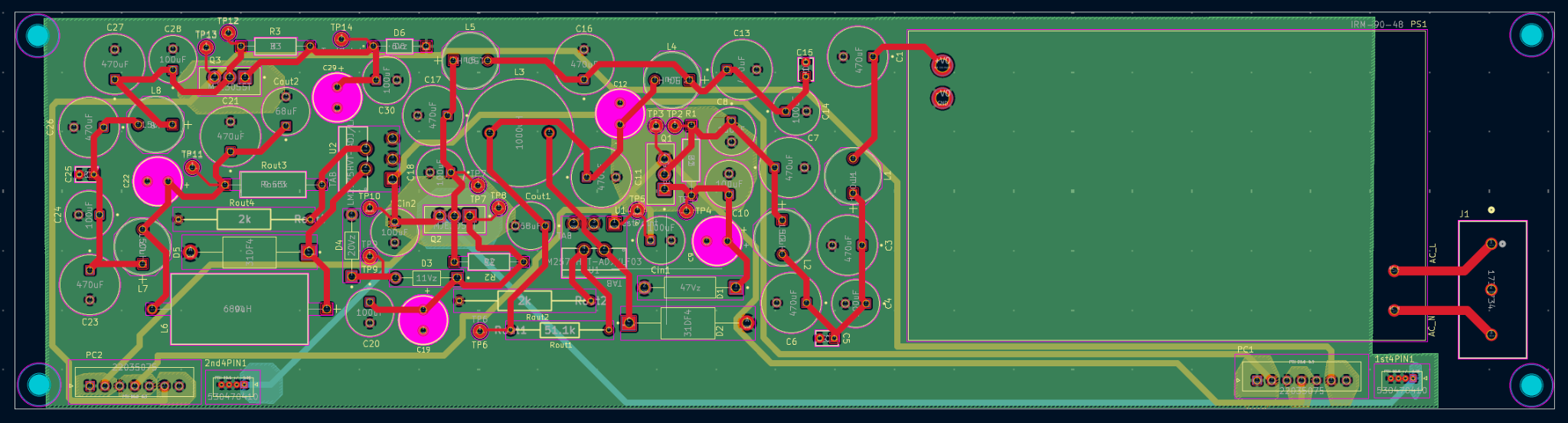
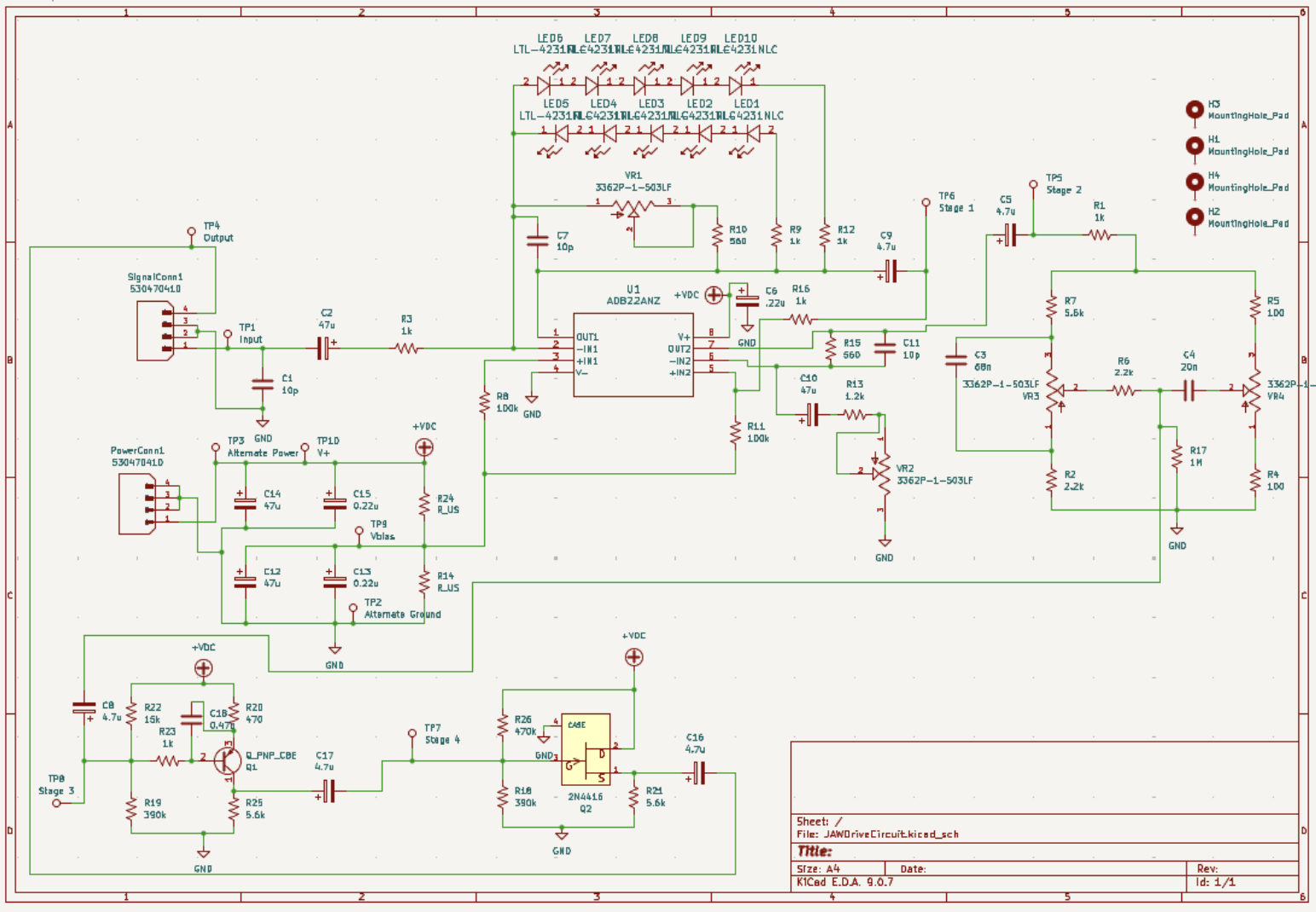
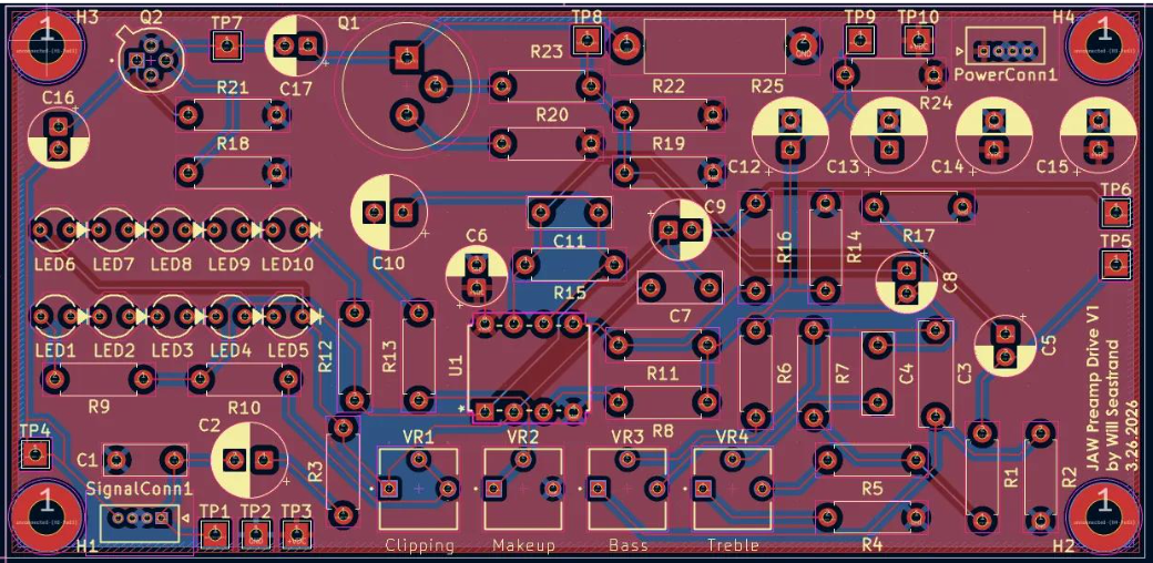
Drive Effect Circuit
Despite the primary goal of the project being transparent amplification, the customer wanted the option to color the signal with the preamplifier before it goes to his recording device.
- This circuit was designed to reside within the corner of the main PCB, with controls for diode soft clipping amount, bass and treble controls, and makeup gain.
- The final stages of the drive circuit utilize a Germanium BJT Transistor and an N-Channel JFET, both biased to lightly clip the signal, adding a characteristic warm tone.
- While much of the recording industry is standardized, custom-designed effects such as this are important for musicians and recording engineers to develop a unique, recognizable sound.
Acknowledgements
Thanks to Ignacio Molino, Professor Dan Phinney, Professor Michael Heilemann, Professor Stephen Rosessner, Professor Sarah Smith, Professor Jack Mottley, Dr. Dave Anderson, Paul Osborne, Kyle Ohlschlager, Abby Che, Glenn Xiong, Michael George, Shea Thorpe, Magdalena Beer, Harrison Candelario, and Logan Cuda for their knowledge, talent, support, and resources throughout this process.