Team Members
- Declan Bhagwat
- Shelinee Hernandez Espino
- Alex Nagy
- Noah Schloff
- Calvin Tourangeau
Sponsors
Patrick Ellsworth

Patrick Zinter

Abstract
Additive manufacturing is an emerging technology that increases the efficiency and lowers the costs of production within the aerospace industry. Companies like L3Harris have begun embracing the capabilities of manufacturing satellite components using this technique. The goal of this project is to design and develop a Secondary Mirror Support Structure (SMSS) that can be fabricated using additive manufacturing, more specifically 3D metal printing. To meet the goals of this project, the team continued from last year’s accomplishments to help influence our initial concept designs. Then a combination of topology, shape, and sizing optimization was used to further progress our designs towards the requirements and specifications outlined by the project sponsor, L3Harris. After reviewing the previous team’s findings, this year’s design progression centered around the use of shelled models – focusing on the load-bearing geometry of the structure rather than internal lattice supports. The report will highlight the iterative design process, finite element analysis (FEA), manufacturing, printability, and supporting testing results. These techniques combined to a model that met all the provided requirements and specifications.
Project Details
Problem Definition
Lightweight secondary mirror support structures (SMSS) require affordable, fast, and structurally sound manufacturing methods, such as additive manufacturing, to precisely align optical components without obstructing the field of view. These mounts are crucial in the advancement of imaging technology, without them knowledge of both the earth and deep space would not be able to grow at the rate it has in this millennium. Current solutions for SMSS use a graphite composite layup which is incredibly expensive and time-consuming. Improving additive manufacturing methods for these SMSS is crucial in the next step in aerospace development as it is one of the most tightly tolerance parts of satellites, so being able to manufacture them with 3D printing will decrease satellite manufacturing time, increase reliability, and increase production.
Requirements and Specifications
Requirements
- The project scope is the design, analysis, and prototype of the Secondary Mirror Support Structure (SMSS) only.
- The project shall focus on additive manufacturing solutions to the problem statement.
- The SMSS shall provide interfaces for and support the secondary mirror and mounts, actuator assembly, shade assembly, and all miscellaneous thermal hardware.
- The design shall be producible with additive manufacturing methods.
- The following design factors of safety shall be used in the analysis:
- Yield: 2.0
- Micro-Yield: 1.0
- Ultimate: 2.5
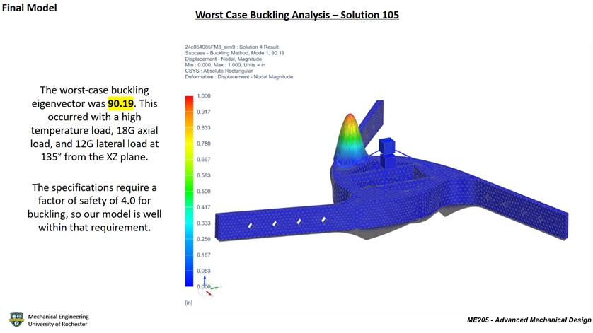
- Buckling: 4.0
- The following mass contingency factors shall be used:
- Concept Design: 20%
- Preliminary Design: 15%
- Final Design: 10%
- Post Final Design: 5%
- Measured Hardware: 0.10%
- There shall be no trapped cavities in the SMSS.
Specifications
| Specification | Verification |
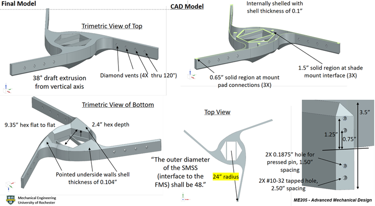
| 1. The outer diameter of the SMSS (interface to the FMS) shall be 48 inches. | An NX sketch of a 48-inch circle around the model will confirm the diameter of the SMSS. |
| 2. The SMSS shall interface to the Forward Metering Structure (FMS) at three locations 120 degrees apart. | The FARO Quantum Max ScanArm will confirm the angles between each mount pad. |
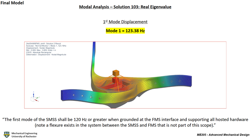
| 3. The first mode of the SMSS shall be 120 Hz or greater when grounded at the FMS interface and supporting all hosted hardware. | NX modal analysis will be used to confirm the first mode of vibration. |
| 4. The mass of the SMSS shall be 18 lbm or less. | The model will be inspected in NX to confirm the mass. |
| 5. The SMSS shall have positive margins of safety against yield and ultimate failure when exposed to a quasi-static load of 12 G laterally and 18 G axially simultaneously (lateral swept 15° increments) combined with a 5°C to 35°C temperature range (nominal room temp is 20°C) while supporting all hosted hardware. | NX will be used to display the yield and ultimate stress for the launch loads described, and then a margin of safety calculation will be performed to ensure positive margins in the worst-case load environment. |
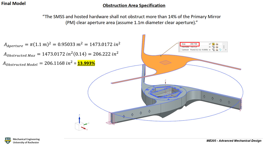
| 6. The SMSS and hosted hardware shall not obstruct more than 14% of the Primary Mirror (PM) clear aperture area (assume 1.1 m diameter clear aperture). | NX will be used to calculate the area of the PM covered by the SM and SMSS. |
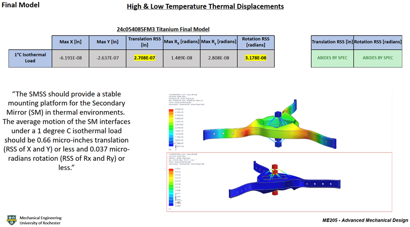
| 7. The SMSS shall provide a stable mounting platform for the Secondary Mirror (SM) in thermal environments. The average motion of the SM interfaces under a 1°C isothermal load should be 0.66 micro-inches translation (RSS of X and Y) or less and 0.037 micro-radians rotation (RSS of Rx and Ry) or less. | The model will be simulated in NX to find the translational and rotational displacements of the SM under 1°C isothermal loading. |
Project Highlights
Initial Design Concepts
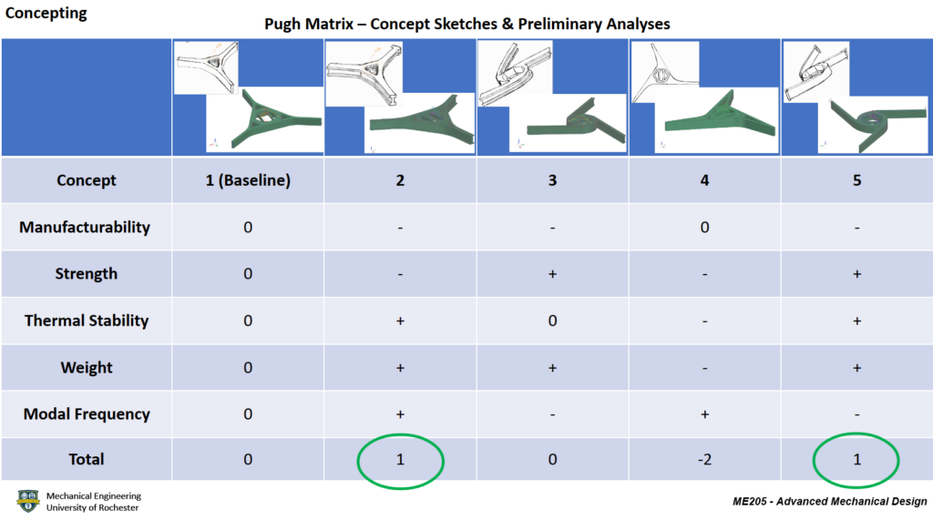
The team created several concept sketches of a potential SMSS which were then made as CAD models with corresponding Finite Element Model (FEM) analysis using NX software by Siemens. The same FEM and simulation characteristics, such as material, mesh size, loads, and boundary conditions, were applied to all concepts. After obtaining all the analysis results, the team compared the performance of all the concepts in a Pugh matrix, using the characteristics of manufacturability, strength, thermal stability, weight, and modal frequency. This comparison process helped the team move forward with further design and optimization of concepts 2 and 5, as these were the designs with the best performance.
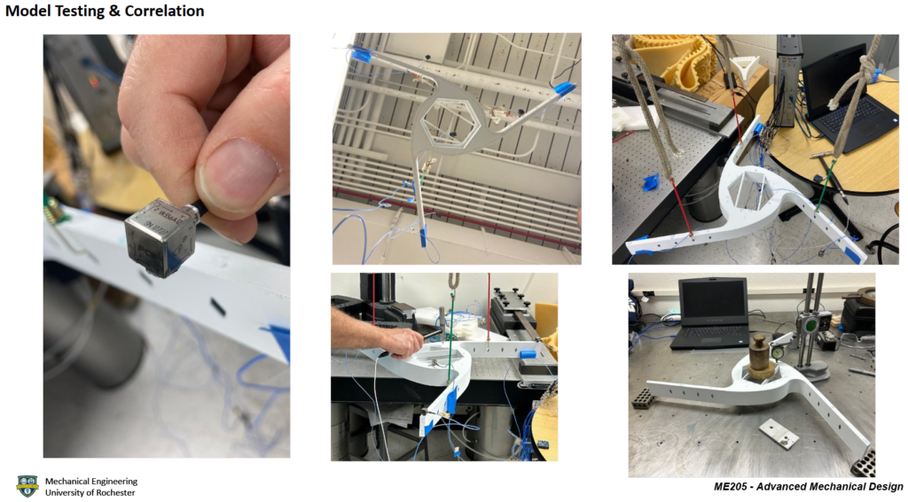
ASA Prototype, Testing, and Correlation
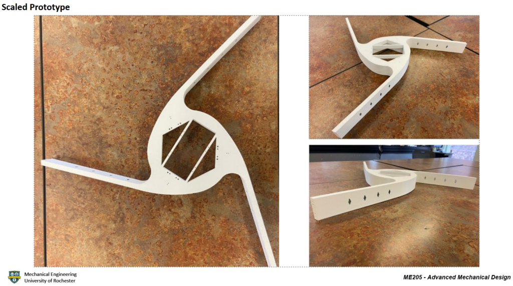
To correlate the finite element model and simulation to a physical model, the team ordered a 60% scaled ASA model from Xometry, on which vibration and displacement tests were performed. Once testing was completed, the team created simulations that resembled similar environmental conditions as those witnessed during each test, to correlate the simulation results to the physical test results. It was found that the percent error of the displacement and vibration test results was less than 1% and 8%, respectively. For more details regarding the procedures and detailed results, please refer to the Model Testing section of the final design review document attached in the Supplementary Documents section below.
Final Model Design & Performance
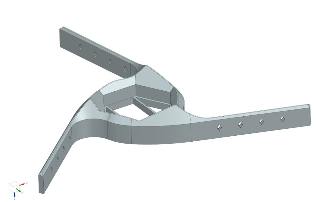
Once the optimization process began, the team determined that concept 5, shown above in the Pugh matrix located in Project Details, would become the sole focus of optimization, as it was found that its parameters were closer to meeting the requirements and specifications in comparison to concept 2. After the team performed several optimization iterations of this design, all the requirements and specifications were met, as detailed in the table and images below. The final shape and geometry of the final model were driven by topology, shape, and sizing optimization as well as printability limitations for 3D metal printing. Please refer to the Final Model Results section on the Final Design Review (FDR) document in the Supplementary Documents section below for specific details about the values obtained from the analysis performed on this model.
| Requirements & Specifications | Verification |
| The outer diameter of the SMSS (interface to the FMS) shall be 48 inches. | The SMSS and hosted hardware obstruct 13.99% of the PM clear aperture area. |
| The SMSS shall interface to the Forward Metering Structure (FMS) at three locations 120 degrees apart. | The FARO Arm recorded 118.07 degrees. |
| The first mode of the SMSS shall be 120 Hz or greater when grounded at the FMS interface and supporting all hosted hardware. | The first mode is 123.38 Hz. |
| The mass of the SMSS shall be 18 lbm or less. | The final mass is 17.70 lbm. |
| The SMSS shall have positive margins of safety against yield failure when exposed to a quasi-static load of 12 G laterally and 18 G axially simultaneously (lateral swept 15° increments) combined with a 5°C to 35°C temperature range (nominal room temp is 20°C) while supporting all hosted hardware. | The lowest margin against yield is 1.53. |
| The SMSS shall have positive margins of safety against ultimate failure when exposed to a quasi-static load of 12 G laterally and 18 G axially simultaneously (lateral swept 15° increments) combined with a 5°C to 35°C temperature range (nominal room temp is 20°C) while supporting all hosted hardware. | The lowest margin against ultimate is 0.93. |
| The SMSS and hosted hardware shall not obstruct more than 14% of the Primary Mirror (PM) clear aperture area (assume 1.1 m diameter clear aperture). | The SMSS and hosted hardware obstruct 13.99% of the PM clear aperture area. |
| The SMSS shall provide a stable mounting platform for the Secondary Mirror (SM) in thermal environments. The average motion of the SM interfaces under a 1°C isothermal load should be 0.66 micro-inches translation (RSS of X and Y) or less. | The RSS is 0.27 micro-inches. |
| The SMSS shall provide a stable mounting platform for the Secondary Mirror (SM) in thermal environments. The average motion of the SM interfaces under a 1°C isothermal load should be 0.037 micro-radians rotation (RSS of Rx and Ry) or less. | The RSS is 0.03 micro-radians. |
| The SMSS shall have positive margins of safety against buckling failure when exposed to a quasi-static load of 12 G laterally and 18 G axially simultaneously (lateral swept 15° increments) combined with a 5°C to 35°C temperature range (nominal room temp is 20°C) while supporting all hosted hardware. | The lowest buckling eigenvalue was 90.19. |
| Design (CAD model geometry) shall be producible with additive manufacturing methods (3D printing). | The final model is producible with blown powder Directed Energy Deposition (DED). |
| There shall be no trapped cavities in the SMSS. | There are no trapped cavities in the SMSS due to radial venting. |
Future Work
Throughout the project, key lessons emerged: meticulous attention to detail in material ordering, comprehensive packaging instructions, and layered review processes can prevent errors and enhance communication. Future teams should consider testing titanium instead of aluminum and steel for improved model correlation. Further, discussions with L3Harris highlighted complexities in post-processing, particularly for closed-shelled parts, where bead blasting may not be feasible and excess powder poses challenges for optical components. Potential solutions include chemical finishing for internal surfaces. Additionally, continued optimization efforts in topology, sizing, and shape can further enhance the performance of the SMSS, despite the current model already meeting initial requirements.