Parallel jaw grippers for the Sawyer Robotic Manipulator lack the degrees of freedom to replicate the motion and flexibility of a human wrist. This project focuses on combining a 6 degree of freedom (DOF) wrist joint using a “Stewart Strut” platform and a parallel gripper.
Abstract
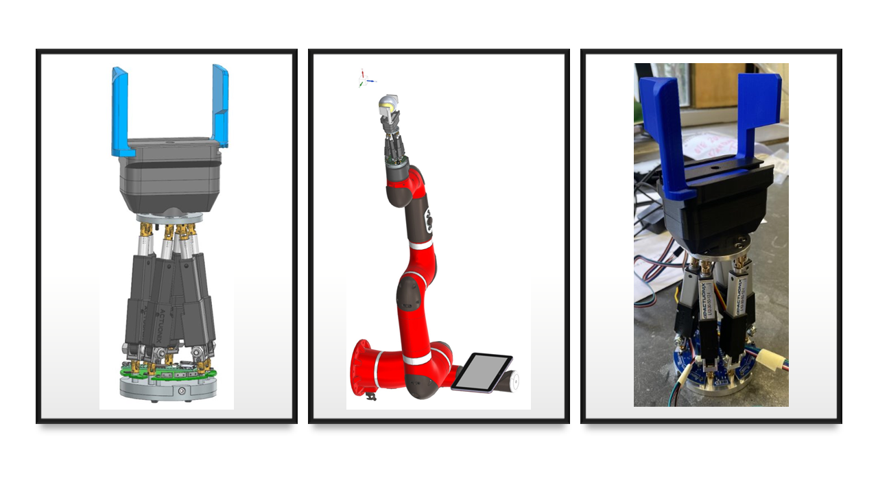
This project addresses the limited dexterity of parallel jaw grippers on the Rethink Robotics Sawyer robotic manipulator by integrating a 6-degree-of-freedom (DOF) Stewart platform with a parallel gripper. The resulting mechanism replicates the complex motion of a human wrist, enabling precise manipulation in tasks requiring multi-axis motion. The design utilizes six Actuonix L12 linear actuators configured in a 6-6 Stewart platform geometry, with aluminum base and top plates connected to the actuators via universal joints. A 3D-printed parallel jaw gripper is mounted on the motion plate for grasping objects, e.g. a tennis ball. Rigorous kinematic, inverse kinematic, dynamic, and FEA simulations were conducted in Siemens NX to validate the concept and ensure mechanical integrity. A Faro Arm was used to verify the system’s compliance with specifications. The prototype achieved rotational capabilities exceeding 30° about the x and y axes, over 60° about the z-axis, and translations of at least 3 cm in the x, y and z directions. The assembly successfully lifted payloads of at least 0.8 kg, remained within dimensional constraints (14.94 cm height, 8 cm diameter), and maintained a total mass of 0.674 kg. These results confirm the design meets all requirements and specifications, offering a viable solution for enhancing robotic dexterity and possibly broader applications.
Problem Statement
Parallel jaw grippers for the Sawyer Robotic Manipulator lack the degrees of freedom to replicate the motion and flexibility of a human wrist. This project focuses on combining a 6 degree of freedom (DOF) wrist joint using a “Stewart Strut” platform and a parallel gripper. The Stewart platform’s unique geometry allows for translation and rotation of a motion plate about any point in space. By attaching a parallel gripper to the motion plate of the platform, a complete hand and wrist mechanism can be created. This problem is important to Professor Thomas Howard, who is interested in such a device to interface with the Sawyer Robot. The Sawyer is designed to perform tasks working alongside humans. By achieving more human-like movements with Sawyer’s robotic arm, the robot’s ability to carry out human tasks can be improved. The project will be carried out in conjunction with an ECE design team for the electronic and programming aspects of the device.
Team Members


Alejandro Porras Díaz
Leo Critchfield
Gustavo Rivera Soto
Tom Whiteley
Project Deliverables, Requirements & Specifications
Project Deliverables, Requirements & Specifications
Deliverables
| CAD Model |
| Kinematic Model |
| Structural Analysis |
| Stewart Platform Subsystem |
| Gripper Subsystem |
| Electrical Subsystem |
| Metrology |
| Test Data |
Requirements
| Motion plate must exhibit motion in 6 degrees of freedom. |
| Mechanical system must interface with the Rethink Robotics Sawyer Platform. |
| Design must allow power and signal wires to pass through uninhibited hexapods. |
| Grippers must be able to grasp and hold a tennis ball. |
| Must enclose MCU, motor controllers, voltage regulators and interfaces. |
| The gripper must be interchangeable on the motion plate. |
Specifications
| Minimum translation in the x, y, and z coordinates in the base frame of 3 centimeters. |
| Minimum rotation about x and y coordinate axis in the base frame of 30° |
| Minimum rotation about the z coordinate axis in the base frame of 15° |
| Maximum device height (cylinder envelope excluding the gripper assembly) of 15 centimeters. |
| Maximum device diameter of 8 centimeters. |
| A minimum payload of 0.5 kilograms to be held securely by the gripper. |
| A maximum mass of the whole assembly (platform and gripper) of 2 kilograms. |
Concept Development & Analysis
Development
Structure and actuator selection
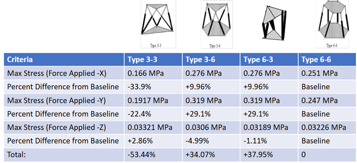
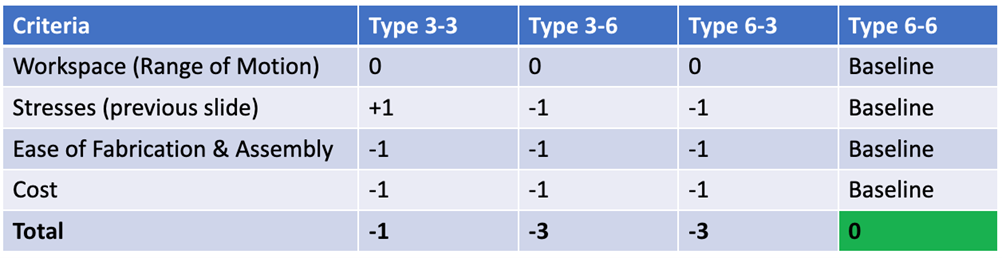
A structural analysis was completed on 4 hexapod configurations (6-6, 3-6, 6-3, 3-3) to determine the most suitable design. Based on its forces and manufacturability, Type 6-6 was chosen. The picture below shows our analysis for one of the configurations.
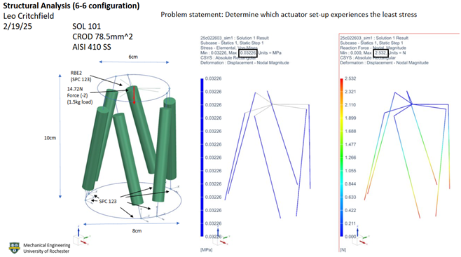
Based on the results a Pugh Matrix was draw and found that the ideal structure to use was type 6-6 despite not being the one that has the least stress, given that it still met the specifications needed for our project.
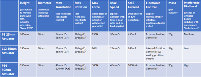
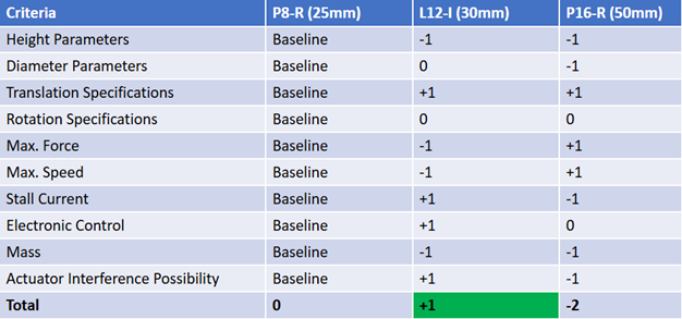
Next, the actuators were chosen with a similar process. With the team’s first CAD iteration, different actuators were used on the model to check parameters and determine which one be the best for our application. Below are the three actuators for which the selection was done.

Based on the results the following Pugh Matrix was draw and had the L12-I as the team’s recommended actuator.
Analysis
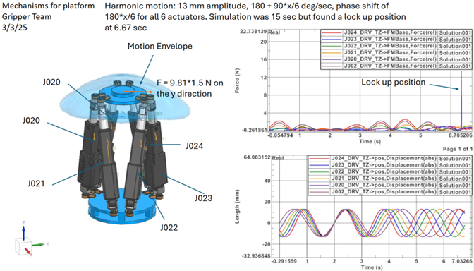
A dynamic model and fatigue analysis were created to evaluate operation of the device before construction. The dynamic simulation modeled worst-case forces acting on the platform and actuators at various orientations using Siemens NX. Using harmonic movement, the maximum force in a single actuator reached 2.5 N during nominal movement and 14N with lockup— both within the L12 actuators’ 22 N capacity.
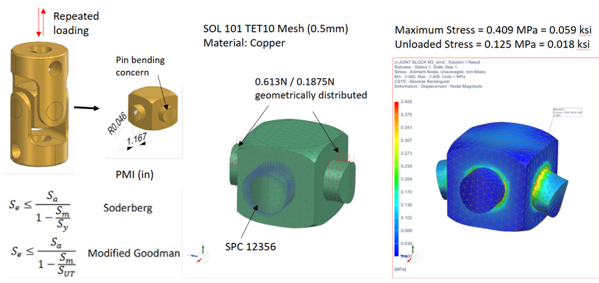
Using the maximum force a single U-Joint pin would experience; the fatigue analysis satisfied the infinite life criterion for both the Soderberg and Modified Goodman methods ensuring no number of cycles would cause failure.
Final Design
After many design iterations due to concerns on space envelope, actuators torque due to motion (causing spin), electronics accessibility, electronics collision, and a quick release for easy mounting on the Sawyer robot, the team came up with a final design. This design included:
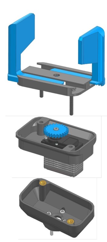
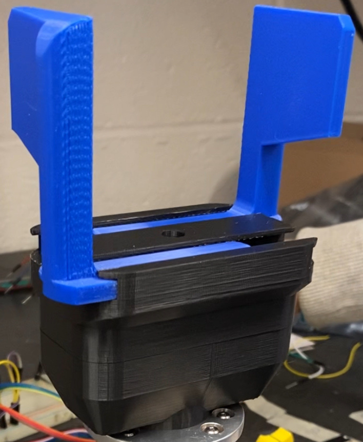
Modular removable 3D printed gripper:
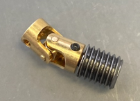
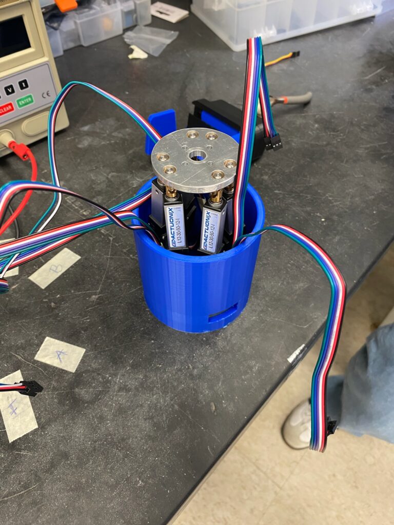
Separated Sawyer and platform base plates, custom actuator connectors (bottom connecting block), universal joints (fixed on base), base plate U-Joints risen with dowel pins and spacers for PCB clearance:
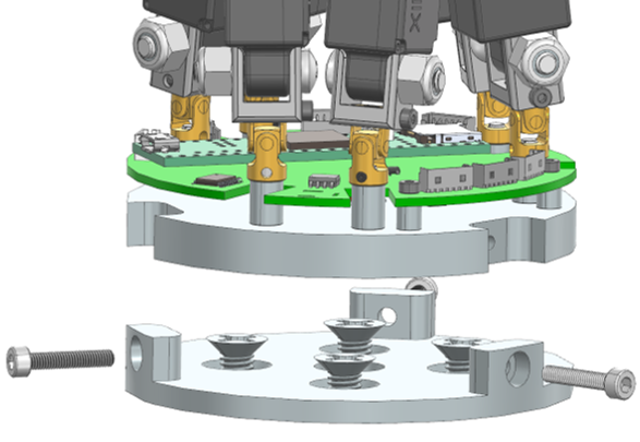
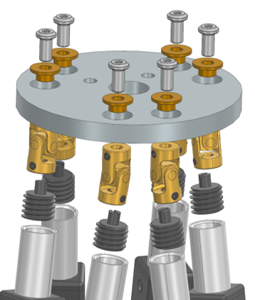
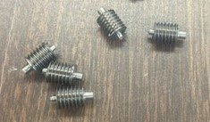
Custom actuator connectors (threaded top inserts), and free to rotate about top plate using with bushings and shoulder bolts:
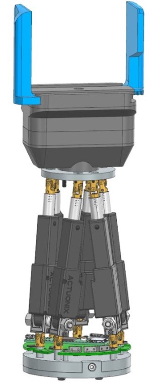
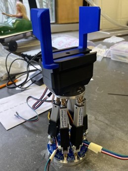
Final CAD & full Assembly:
Device Manufacturing
To efficiently construct the Stewart strut, the team divided machining tasks among smaller groups, with each member responsible for a specific component: Sawyer plate (HAAS CNC Mill -NX Programmed), connecting block (HAAS CNC Mill -NX Programmed), Stewart strut bottom plate (ProtoTrack CNC -manual coding), Stewart strut top plate (ProtoTrack CNC -manual coding), top plate connecting pins (manual lathe).
HAAS 5-axis CNC Mill
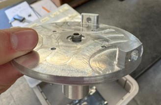
Two of the team members worked on creating the tool paths and generating the G-Code required to run the HAAS 5-axis CNC mill. Each of the team members worked on one specific part, one on the bottom connecting block, and one on the bottom connecting block Sawyer connecting plate. The resulting parts can be seen below respectively.
ProtoTrack CNC Mill
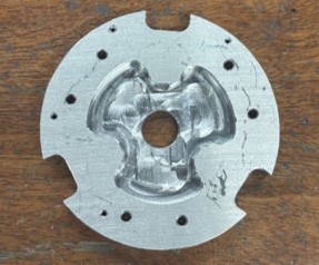
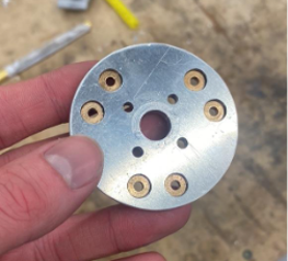
Another of the team members focused on manufacturing the top and bottom stewart strut plates using the manually programmable ProtoTrack CNC mills. This was because instead manufacturing with this specific CNC would be much faster as unlike the HAAS CNC mill there is not as extensive review process to manufacture the parts, allowing the team to move faster in the manufacturing of the device. A picture of the bottom and top plate can be seen below respectively.
Manual Lathe
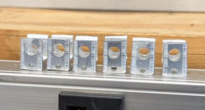
Another team member was responsible for making top connecting pins, manufactured using the manual lathe. An 8mm rod with the correct thread was purchased and the processed on the lathe via different operations until the pins were made.
3D Printing
Another teams member was responsible for 3D printing and assembling the gripper. Apart from the screws, the heat inserts and motor, the entire gripper is 3D printed.
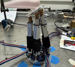
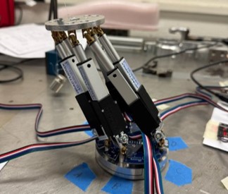
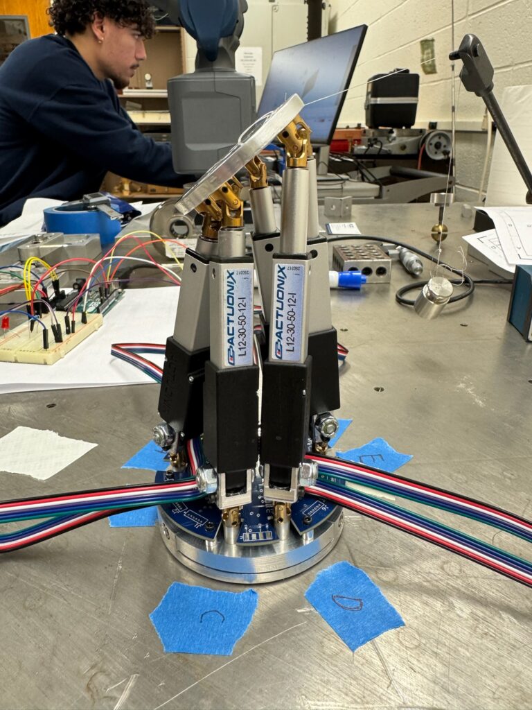
Final Device (without ECE’s board and circuits)
Testing
The Quantum X FaroArm® located in Gavett 121 (within the University of Rochester Mechanical Engineering Department) was utilized to scan the assembly and measure displacements relative to the base coordinate axis, ensuring accurate data collection. Prior to scanning, spacers were placed between the table and the assembly to eliminate calibration errors during testing. The system was calibrated by measuring four points on both the base and top plates to define the base coordinate planes. The Stewart Strut platform was then moved to its extreme positions by controlling the actuators in order to capture the system’s maximum range of motion. At each of these positions, the top plate was scanned using the same method employed for the base coordinates. Data was collected by measuring the distance or angle between the reference plane (at the zero position) and the planes corresponding to translated, tilted, or twisted configurations.
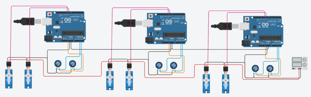
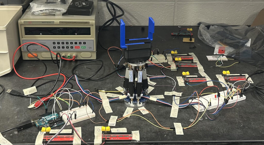
Electrical Circuits
Although the electrical and computer engineering team was responsible for controlling the Stewart platform, a simple control system was developed to collect preliminary test data. This system involved controlling each actuator using an Arduino, linear potentiometer and a power supply. A control code was created to operate the actuators through an interfacing linear potentiometer.
Methods of Testing
The Quantum X FaroArm® was used to scan the Stewart Strut assembly, measuring displacements relative to the base to verify range of motion and system accuracy. The setup involved calibrating both base and top plates and actuating the platform to its extreme positions to capture maximum translation, tilt, and twist. Testing confirmed that all design specifications were met, including the expected Z-translation limit of three centimeters due to actuator stroke constraints.
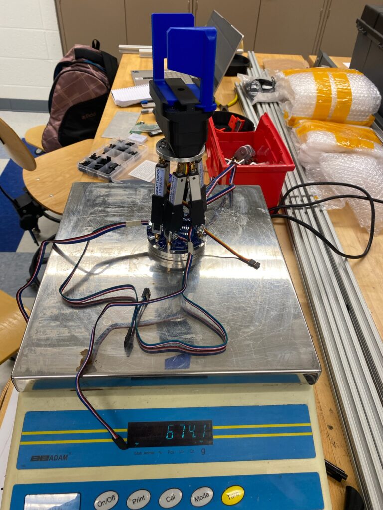
Next, the size constrain (diameter) was tested by having a 3D printed 8cm cylinder and checking that the device fitted inside the agreed envelope (diameter only, as height was also checked with the FaroArm). The device weight was also checked using a scale and made sure that it was not over 1.5kg, as the entire device plus payload had to be 2kg at maximum and a minimum payload of 0.5kg was required.
Testing Videos
The two videos below show early tests of the gripper working and making sure a tennis ball could be held in place, as well as the platform moving (sped up). The control system from the Electrical and Computer Engineering team is design to move the platform a lot faster. The Mechanical Engineering team’s simple circuit was just used to show proof of a working device and to drive it to testing positions.
Following the testing process, it was concluded that the system fulfilled all specified requirements. The test data is presented in the table below. One important consideration related to the data is that the Z-translation was rounded to three centimeters, aligning with the precision defined in the specifications. It was also confirmed in agreement with the sponsor during the selection of the Actuonix L12 actuators that a Z-translation equal to or greater than three centimeters would be physically unachievable due to the platform’s geometry, as the maximum stroke length of each actuator is limited to three centimeters.
| Specification | Required | Tested | Pass/Fail |
|---|---|---|---|
| Minimum translation in the x, y, and z coordinates in the base frame. | 3 cm | Z: 2.93 cm X: 4.3 cm Y: 4.1 cm | PASS |
| Minimum rotation about x and y coordinate axis in the base frame. | 30° | X: 33.1° Y: 38° | PASS |
| Minimum rotation about the z coordinate axis in the base frame. | 15° | 60.8° | PASS |
| Maximum device height. | 15 cm | 14.94 cm | PASS |
| Maximum device diameter. | 8 cm | 8 cm | PASS |
| Minimum payload to be held securely by the gripper. | 0.5 kg | 0.8 kg | PASS |
| Maximum mass of the whole assembly. | 2 kg | 0.674 kg | PASS |
Recommendations for Future Work
Design Improvements
In terms of design, the base plate configuration has the largest room for improvement. To begin, the connection between the sawyer base plate and the platform base plate could be simplified and better constrained. Rather than using three screws with extruded knobs, which requires the aluminum knobs to bend inward to fully constrain the plates, a latch connection could be used with only one fastener. This would lessen the material needs of the two plates and better constrain the plates together.
Another improvement to the base plate configuration could be shelling more material out of the center of the platform base plate. There is only a need for material on this plate in a thin outer ring where the dowel pins, PCB screws, and sawyer plate connection lie. Otherwise, material in the center could be completely removed to save weight. Having a gap in the middle could also leave room for the PCB to be sunk into the base plate, rather than sitting on top of the plate. This could allow the dowel pins to be shorter, lessening their chance of bending and failure, and would reduce the total height of the device.
Manufacturing Improvements
In terms of manufacturing, there could be an improvement on the way that the sawyer plate and bottom plate are manufactured and assembled. A suggestion to improve the process is to machine each of the two parts profile individually first (no side holes to connect them). Then make sure they fit together properly and make a boss to hold both pieces together through the middle hole they both have. Once that is done, they can be machined as an assembly. First on the lathe to get a flush and clean finish and then on the mill alongside an indexing head to drill the side holes all together. This would ensure that the holes are perfectly aligned and at exactly 120 degrees from each other. In the prototype presented on this paper, this was not the case and when assembling, the user must make sure to align the witness holes on the side to make sure both parts fit together with no issues and can be screwed easily.
Moreover, another suggestion would be to make the universal joints from scratch. Making them this could allow the user to machine, say on of the universal joints side and the connecting pin as a single part removing the need of set screws which have proven to be complicated to work with due to size of the device. In a similar way, the press fitted pins, risers and universal joint on the bottom plate could all become a single part making it stronger and easier to work with. When making these part and additional alignment feature could be added so that the actuators position is defined from the start. In the current assembly, this causes some issues as the user must align them and perfect alignment cannot be guaranteed as it is all done by “eye”.
Acknowledgments
Team Gripper acknowledges and is greatly thankful to the following people for their help and advice in our project:
- Professor Christopher Muir (Project Sponsor and Advisor)
- Professor Thomas Howard (Project Custumer)
- Jim Alkins (Manufacturing Advisor)
- Bill Mildenberger (Manufacturing Advisor)
- Samantha Kriegsman (Manufacturing Advisor)
- Alex Prideaux (Administrative Advisor)
- Christine Pratt (Administrative Advisor)
- Sebastian Gomez (Teach Assistant Advisor)
- Omar Zakaria (ECE team member)
- Will Knoff (ECE team member)
- Hesham Elshafey (ECE team member)