Table of Contents
- Abstract
- Members
- Mechanical Analysis
- Manufacturing
- Results
- Project Report and Presentations
- Acknowledgements
Abstract
High-energy-density phenomena are not fully understood yet by the scientific community. The Laboratory of Laser Energetics (LLE) at the University of Rochester seeks to amend this gap by conducting experiments regarding the optical reflectivity of such substances.
A light relay apparatus was designed and manufactured to assist with these experiments, such that light could be relayed from a backlighter sample to an experimental sample from which the reflectivity would be measured. This apparatus performed successfully in the experiment, prompting usage in future experiments, albeit with the potential for revisions to simplify the manufacturing process.
Members
Project Sponsor
Design Team
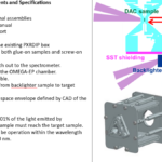
Design Task
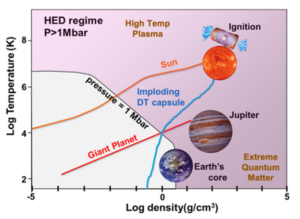
The Laboratory for Laser Energetics (LLE) is a scientific research facility that operates lasers to conduct a variety of experiments. The LLE studies high-energy-density (HED) substances to gain insights into material properties under high pressure and temperatures.
The team was tasked with developing a mechanical apparatus to relay the light from a back-lighter to a HED sample so that the reflected light can be measured to understand the reflectivity of the sample.
The success of this experiment will provide a better understanding of hydrogen’s transition from opaque to metallic reflective properties.
Mechanical Analysis
Tolerance Analysis
A tolerance analysis was performed on the tab holes that interface with the 2-56 screws. The tolerance grade of the hole was used to determine the proper tolerance of the hole diameter on the tab.
The resulting analysis determined that the hole should have a maximum tolerance of 0.01 mm, and a 0 mm minimum tolerance. Using the results from the tolerance analysis, the specific dimensions like the tab width and the hole locations could be determined.
Fatigue Analysis
A fatigue analysis was also performed on the tabs. The endurance limit was calculated and plotted against the Soderberg and Modified Goodman line to predict its lifetime.
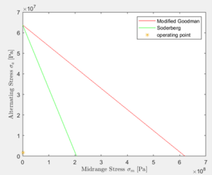
According to the fatigue analysis, the endurance limit was 63.8 MPa. The necessary endurance limit according to both the Modified Goodman and Soderberg methods were both 1.7 MPa. Both Modified Goodman and Soderberg criteria predict infinite life, which indicate that the tabs will never be close to fatigue under operating conditions. This analysis confirmed that the tabs are not a critical component when it comes to the assembly, and hence it is acceptable to have a bit of variability in manufacturing quality.
Beam Analysis
A fundamental mechanical analysis was also performed on the tabs. The tabs were modeled as a cantilever beam, with its base fully constrained and a load applied at the free end.
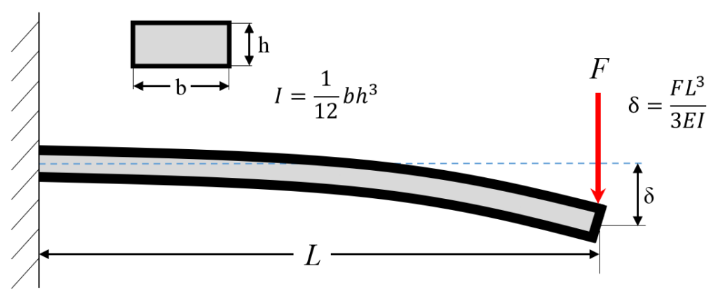
A cantilever beam model was chosen because the tabs were designed to be fixed at one end with a force being applied on the opposite end to simulate the weight of the optics. A factor of safety of 3 on the weight of the optic was chosen, and displacement was calculated to ensure the optic would be held in place if the reflectivity box was held upside down or rotated in the laser target chamber. The displacement under the applied load was calculated to be 0.000418 mm.
Because the displacement at the end of the tab was not greater than the thickness of the optic, it was determined the tab design could secure the optic. This analysis also confirmed a 0.005 in tab thickness was sufficient and other types of shim stock material could be utilized in the design of the tabs.
Finite Element Analysis
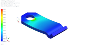
A structural FEA linear statics analysis on the mirror tab was conducted to investigate if the tab could support the weight of the optic. Maximum and minimum stresses were computed to verify the tab would not deform inelastically under the weight of the optic utilizing Von-Mises criterion.
Displacement was also measured to ensure the optic could not slip out from underneath the tab from an applied force of 0.122 N.
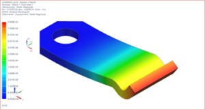
The convergence study resulted in a maximum stress of 3.406 MPa, minimum stress of 0.001 MPa, and displacement of 8.087*10-4 mm. The results indicate the optic can be held in place by the tab without deforming inelastically and slipping out.
Manufacturing
A total of eight sets of assemblies were manufactured, and each component involved in the assembly were manufactured as follows:
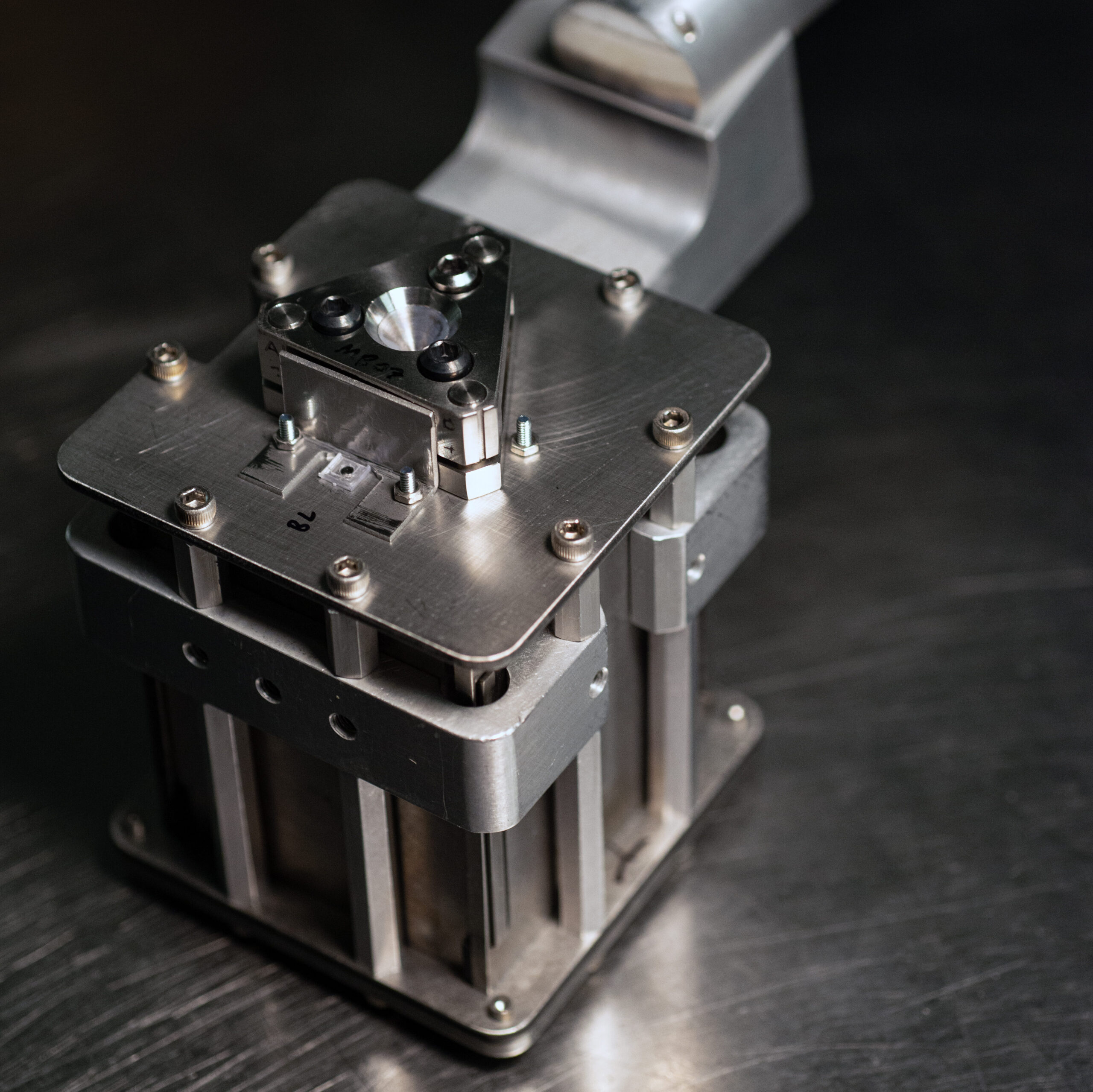
Reflectivity Box
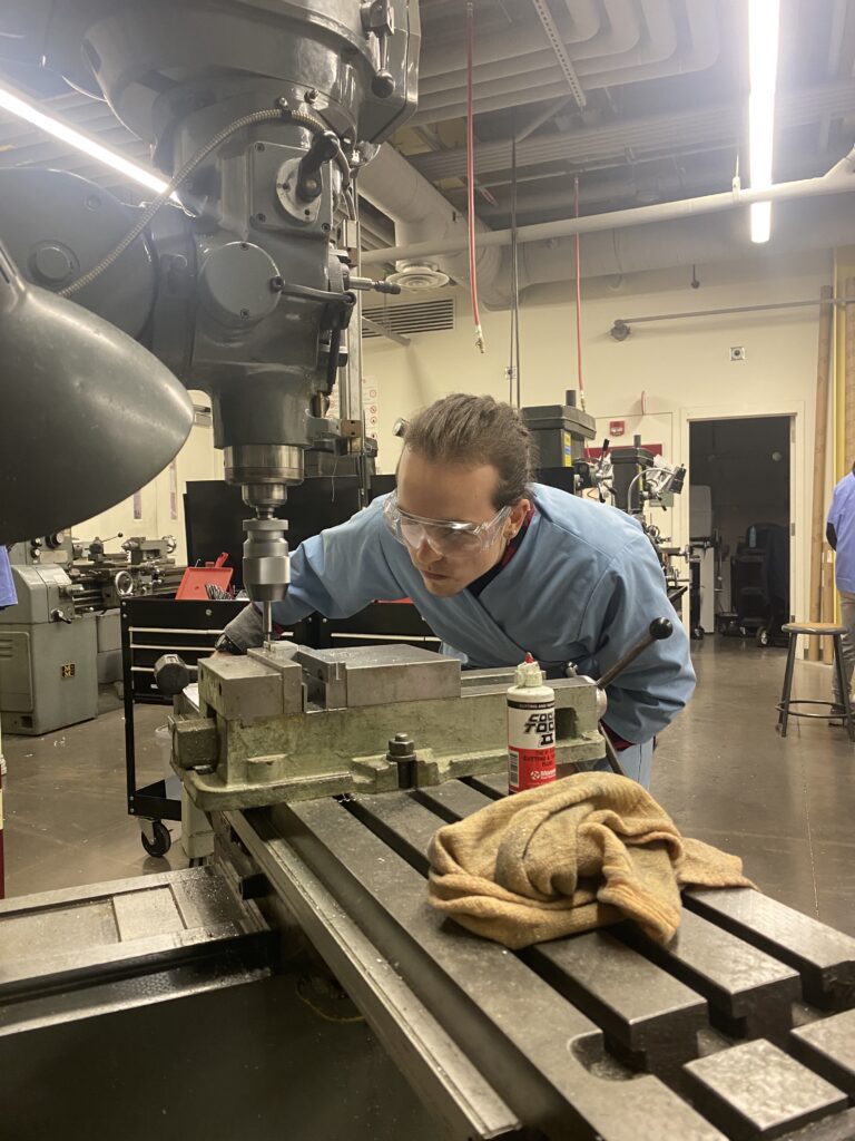
The reflectivity boxes for the light relay were manufactured using the 4-axis CNC machine, and were then cut to size, and the cut surface was finished again on the CNC machine. After the surface finish, the threaded holes were tapped by hand.
Aluminum 6061 was used for the reflectivity box because of its ease of manufacturing compared to other metals, its ubiquity, and the high reflectivity of the material, which would add to the effectiveness of the light relay.
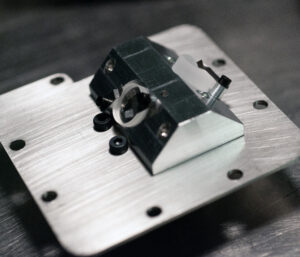
Front Plate
The front plates were first cut to shape from a sheet of SAE 304 stainless steel using a waterjet cutter. The edges were then finished on a deburring wheel, and the holes were drilled using a mill.
Shield
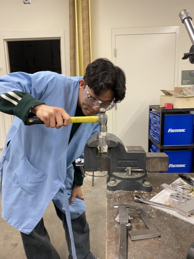
The shields were also cut to shape out of a sheet of SAE 304 stainless steel using a waterjet cutter and the rough edges were deburred using belt sander and a file. The flat shields were then clamped on a vice and hammered to a 90-degree angle along a bend line.
The holes on the shield were then drilled using a mill, and an end mill was then used to open up more of the initial shield cutout so that there would be enough clearance for the backlighter sample to be mounted on the front plate without interference from the shield.
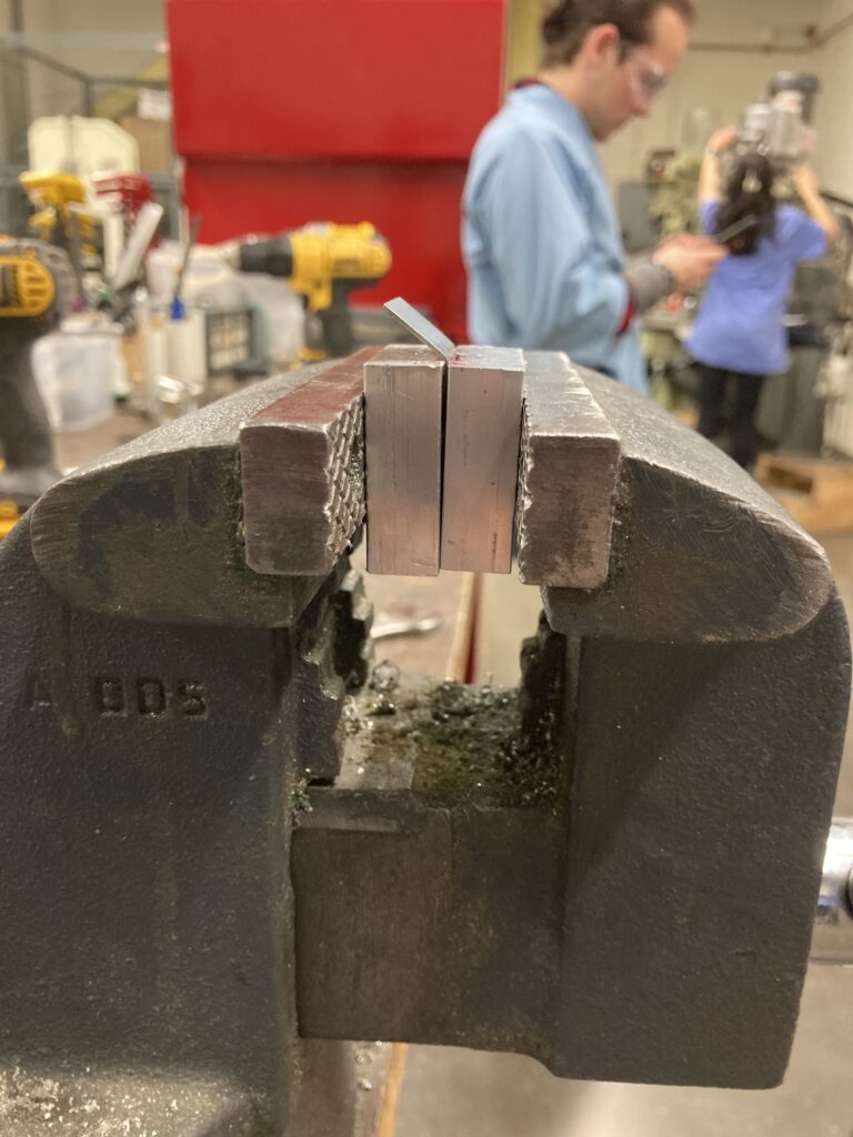
Tabs and Spacers
The spacers were manufactured entirely on a lathe out of a thin aluminum rod. First, one of the ends was finished to be smoother. Next, a hole was drilled at the center of the rod and the material on the outermost layer was removed to shape the spacers to the proper exterior diameter. The machined rod was then cut to the proper length using a part splitter.
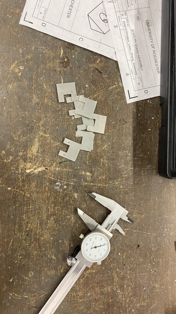
The tabs were made out of shim stock, and they were cut to their shapes using a shear cutter. The holes in the tab were located using a center punch, and were cut using a stud punch. The tabs were then bent to shape using pliers.
The spacers and tabs are used in conjunction to hold the mirror and the beam splitter in place on the reflectivity box.
preparing to mill an extra hole on a reflectivity box
finishing the final face of a reflectivity box
drilling holes in a front plate
bending a shield
preparing to drill holes in a shield
bending a shield
the waterjet cut shields, before bending and drilling holes
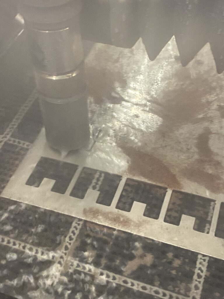
waterjet cutting the shields
Results
The light relay apparatus was successfully used as a crucial component in an experiment held at the LLE on April 16, 2024. Here are some key results from the experiment.
Functioning Light Relay
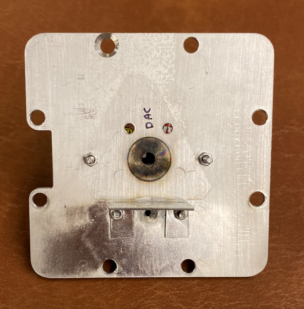
The most critical piece in the final assembly was the reflectivity box which held the mirror, the beam splitter, and had an internal channel that collectively formed the light relay that would channel the light from the backlighter to the target. To ensure the final experiment was a success, the light relay within the reflectivity box had to function properly.
The pictures here show an image of the front plates after they were used in the laser experiment. The scorch marks shown in the target hole on the front plate shows that the light relay within the reflectivity box was indeed functional.
Experiment Insights
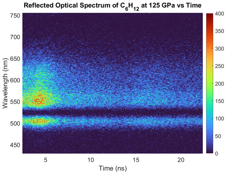
This is a visual representation of the data collected from the laser experiment that the hardware was used for. It plots the intensity of the wavelengths of the laser light against pulse duration. The color bar on the right shows the intensity in units of analog digital units or ADU, where 1 ADU is 1 photoelectron, and 1 photoelectron is 1000 photons entering the telescope.
The results from the experiment confirm that the hardware met the given specifications. It can be seen on the plot that the signal from the laser is quite apparent, which would not be the case if the efficiency was below 0.01%. In addition to that, the plot also shows the signal being well within the 450 to 750 nm range. The efficiency drops at the edges are due to the diagnostic response.
While the exact numerical values are unknown, the higher motivating goal for the project was to measure the broadband reflectivity of laser compressed HED material in a DAC. As this goal is what inspired the hardware design requirements, which were clearly met according to the experimental data provided.
Project Reports and Presentations
Below are links for the final report and the final presentation of this design project. The report has detailed information on the steps involved in the planning, designing, analyzing, and manufacturing stages. The presentation is a quick overview of the design project, and there is also a video of the team members giving the presentation.
Final Design Report (FDR)
Final Presentation
Acknowledgements
The team would like to thank Professor Muir, Professor Mohammad, and Dr. Neel Kabadi for their guidance, as well as Jim Alkins, Chris Pratt and Bill Mildenberger for their help with manufacturing. The team also thanks the engineers at the LLE, especially Jarrett Shamlian, who provided crucial feedback regarding the design.