URMC Orthopedic Rehab Senior Design Team
Jose Luis Corredor Alvarez, Keagan Hemsley, Gabriel Lundy, and Joseph Moore
Mentor
Monica Zaso
Abstract
The objective of this senior design project is to improve rehabilitation via a wearable device that assists the fingers of the human hand to complete its range of motion and return impaired hands to their original strength. Currently, at the University of Rochester Medical Center there are no methods of manually opening fingers. The current solution involves electrical stimulation which activates the muscles in the hand to make the fingers open, but it cannot be used on patients with implanted electrical devices (pacemakers) or patients with a history of seizures. Throughout the semester, the team came up with several design concepts, some of which were selected for further development. CAD modeling of each part allowed for various mechanical analyses in Siemens NX. The parts were 3D printed and assembled into prototypes. After several iterations, the team tested multiple specifications at the on-campus fabrication lab at Rettner Hall.
Problem Definition
Patients with extensive damage to their hand or neurological problems that affect hand muscle control (such as patients who have experienced a stroke) need an assistive device that aids in opening their hand from a closed position and measures their range of motion by measuring the angles of their joints. Making a hand exoskeleton to improve the rehabilitation process will allow patients to open one finger, for pointing or touching, or multiple fingers to grasp something.
Requirements and Specifications
| Requirements | |
| 1 | The device must measure the range of motion of the fingers. |
| 2 | The device must fit an adult hand. |
| 3 | The device must aid an individual or multiple fingers in flexion. |
| 4 | The device must exert an adjustable force to aid in flexion. |
| 5 | The device must prevent the hyperextension of finger joints. |
| 6 | The device must be portable. |
| 7 | Stretch goal: The device must aid in the abduction of the fingers |
| Specification | Value | Description |
| 1 | 1 lbf | The device must have an overall weight of one pound or less. |
| 2 | 180 degrees | The device must have a maximum range of motion of 180 degrees per joint, where 180 degrees signifies the hand being completely open. |
| 3 | 2 degrees | The device must have a joint angle measurement resolution of 2 degrees or better. |
| 4 | 6 lbf | The device must apply a maximum force of 6 pounds to the fingers to aid in finger flexion. |
| 5 | 1 hour | The device must have a battery life of 1 hour under continuous use. |
| 6 | NA | The device must fit a glove size large (male) under the guidelines of the universal glove sizing chart. |
| 7 | 30 Degrees | Stretch goal: The device must have a maximum angle of abduction of 30 degrees. |
| 8 | 3 lbf | Stretch goal: The device must apply a maximum force of three pounds to aid in abduction of the fingers. |
Design Concepts
Hand Frame:
Design 1 – Hand Frame with Wrist Mount
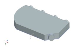
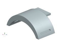
This design integrates a wrist mount to allow for the entire exoskeleton’s weight to be distributed over a larger surface area and so that it can secure to the user without interfering with their hand’s function. The wrist mount is fastened to the user’s wrist using a Velcro strap that is fed through 2 holes on the wrist mount. The wrist mount is then connected to the hand frame via a joint that allows the user to move freely in the rotational y-direction. The hand frame itself has little features and acts as a base for the movement apparatus to be installed directly onto it. This “open” area on the hand frame allows for design iterations to match whatever qualifications are needed to install the movement apparatus.
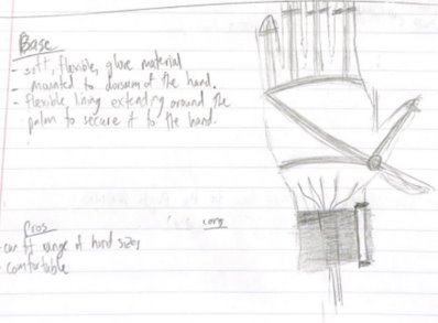
Design 2 – Z Strap
The base can be adjusted to fit a range of hand sizes since it will be made of a soft flexible material similar to that of a glove liner. The lining extends around the palm in a “z” pattern to secure it to the hand. The wristband has Velcro to adjust the tightness and has slots to funnel the cables through, making it more compact. Benefits include that it is a lightweight, comfortable design that allows for multiple hand sizes.
Design 3 – Glove Base with Plastic Rings
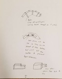
This design will be a glove (store bought) that has been attached to plastic or metal rings that encircle the fingers between the joints. These rings will pull back on the fingers to make them flex.
Finger Module Design Concepts:
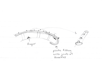
Design 1 – Jointed Hook with Eye Rings
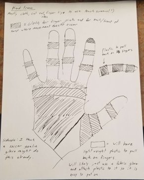
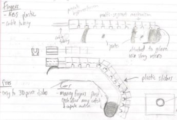
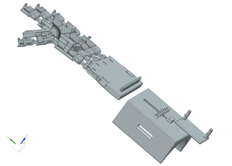
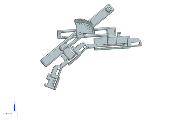
This design features a hook-like apparatus that is fastened to the user’s finger(s) via 3 Velcro straps between each knuckle of the finger. Each segment of the finger module is separated at the knuckles of the finger by a joint that allows free movement in the rotational y-direction (See Figure _ for the base point to be used in this iteration). Installed along the top of the module are 6 eye rings, with 2 located between each knuckle. The eye rings allow for a wire to be fed along the top of the module to allow for the movement apparatus to pull the finger to 180 degrees. The wire is fastened to the last eye ring at the tip of the finger to ensure that it is stuck in place when it is pulled. Another feature of this design is a light padding on the inside of the tip of the hook. This allows for the user to have some comfort as their finger is being pulled open. A possible iteration for this design includes the addition of enlarged joints at each knuckle with degree readings that allow for the specific range of motion to be read at a certain point in the finger flexion.
Design 2 – Metal Locks with Detachable Goniometer
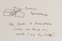
This design will have a series of fisheye holes for a string/cable to run through to guide the string from the tips of the fingers back to the movement apparatus. The fingers will also have plastic loops around them for the string to pull back on and will use thin, lightweight metal rods along the sides of the fingers to prevent hyperextension. A goniometer will also be able to be snapped on and off the metal rod at the joints to measure range of motion. The rods will have a groove in the top and bottom of them for the goniometer to snap into.
Design 3 – Multi-Segment Mechanism (Figure 11 in annex)
This concept is based on a multi-segment mechanism of hard ABS plastic blocks. They are connected via small rotational joints and will have cable tubes embedded in the center to guide the cables required to open the hand. The cables are fastened to the final block on the dorsal side of each fingertip. Cutouts in the segments provide space for the structure to curl. The mechanism is located along the top of each finger. The fingertips will be surrounded by rigid material to assist the fingers when pulled. The benefits of the design are that the sliders are easy to 3D print and the segments do not allow for any hyperextension.
Movement Apparatus:
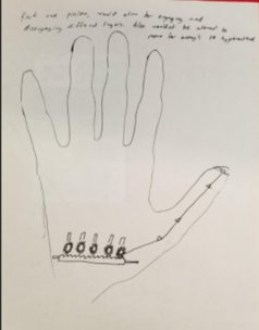
Design 1 – Manual Ratchet System This design will utilize a simple ratchet system. Each winger will be tied to a peg. The peg will be housed in a slot and will be able to slide backwards. An internal ratchet system will prevent the peg from sliding forward again, thereby applying force to the fingers. When the fingers eventually need to be released, the ratchet will have a release mechanism to release the peg and therefore the fingers.
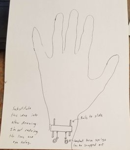
Design 2 – Rack and Pinion
This design will utilize a rack and pinion. Each finger will be tied to a pinion. These pinions will be connected to a rack. The patient will simply have to slide the rack to the side and the pinions will rotate, applying force to the fingers. If individual fingers need to be flexed, the pinions will be able to slide away from the rack so that those fingers will not have their corresponding strings tightened, and therefore no force will be applied to those fingers.
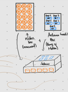
Design 3 – Servomotors
This design uses a (or several) servomotors to pull cables that will generate the extension and abduction of fingers. The servos will be comprised in a box at the base of the hand/wrist. Some of the cables will pull through each finger for extension, and others will pull on the first part of the finger modules at either side of the fingers to generate the abducting motion.
Prototype Timeline
Iteration 1
The first iteration of the design was manufactured using a Prusa 3D printer in order to get a basic understanding of the initial design of the hand mount and finger modules. We used the the pros and cons of this iterations to decide what aspects of the part needed significant changing and what aspects were ideas that we could use in the next iteration.
Iteration 2
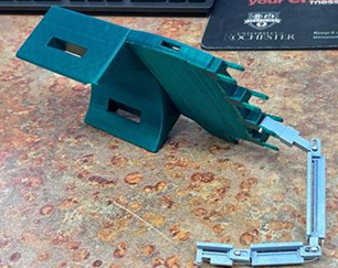
Iteration 2 was our first attempt at attaching the wrist mount to the finger modules. This prototype presented multiple aspects that needed to be redesigned. The major take away from this iteration was the joints on the frame that connected to the finger modules needed to be much stronger, as they were breaking with very little applied force. This iterations was also our first realization that fitting hard plastic to the intricate dimensions of a hand can be very difficult.
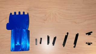
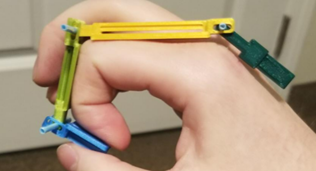
Iteration 3 Final Design
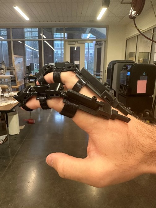
Our final prototype was manufactured on a much more precise 3D printer that has a tolerance of .001 inches, which gave us the ability the be very precise with our design.
The final assembly fits an adult large hand and works as intended but would require more time and iterations in order to be useful in a rehabilitation setting.