
Project Overview
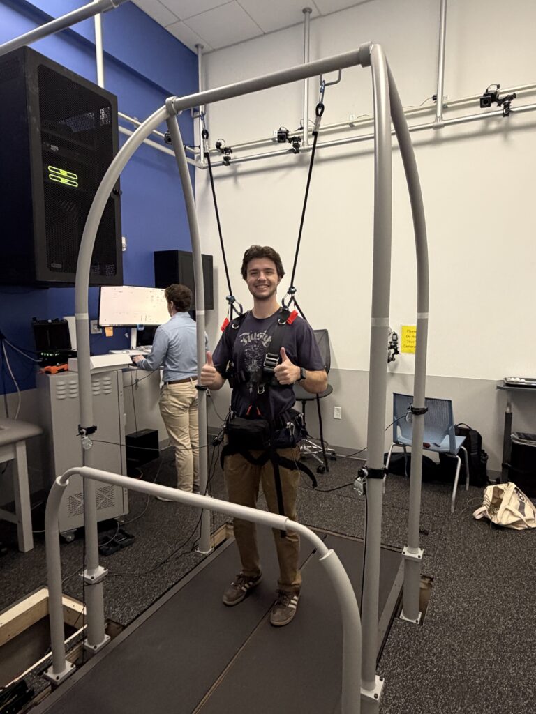
The team worked with the sponsor (University of Rochester Medicine Motion Analysis Laboratory) to engineer and develop a prototype of an integrated harness for their perturbation device as well as streamlining and modifying other pieces of equipment already in use by the lab. A perturbation device is a piece of exercise or rehabilitation equipment designed to apply controlled, destabilizing forces to a person’s body to challenge and improve balance, stability, and reactive postural control. This device is used to simulate real-world balance challenges and enhance neuromuscular responses.
Problem Statement
The University of Rochester Medicine Motion Analysis Laboratory studies the kinematics of human motion and develops experiments and therapies to help understand stability and to improve movement.
Controlled perturbations allow measurement of response timing, compensatory strategies, and joint loading patterns. By improving current features such as alignment of the frame, harness design, cable management, and the VR environment, using the perturbation device will be efficient for both the healthcare provider and the patient.
It is necessary that patients seeking help from the Motion Lab can receive effective care. By making a device that is more streamlined, more robust, and safer, the lab will be able to see more patients, and in the end, help more people.
Deliverables, Requirements, and Specifications
At the end of the project, the following items were delivered to the University of Rochester Motion Lab:
- Functional prototype – This will include a frame, a harness, and load cell/amplifier placement on the frame and harness
- Technical report with test data
- Theory of operation manual
To ensure the correct design and success of the project, certain requirements are defined in consultation with the customer (University of Rochester Motion Lab) and supervisor (Professor Muir). The requirements are as follows:
- Mounting plates on the frame must be aligned
- Harness must fit the 5th to 95th percentile of male and female body types in the US and be able to measure patients at the hip with motion trackers
- Packaging for load cell wires will be clean and will not interfere with the tension in the paracords
- Device must be able to disturb a gait and catch a fall safely
- Prototype must be designed robustly for continuous everyday use
- Patients must be able to be pulled in the cardinal and ordinal directions
To design and build prototypes to meet the mentioned requirements, certain specifications are determined and confirmed by the customer (University of Rochester Motion Lab) and supervisor (Professor Muir). The specifications are as follows:
- The designed components will be built by ensuring a factor of safety equal to 2 times the applied force
- The harness, frame and any other deliverables must maintain functionality when the treadmill is inclined up to 9 degrees
- The adjustment increments for the height adjustment of the pulleys will be no greater than 2 inches
- The harness will allow for adjustments such that the angle of the patient’s knee does not go past 90 degrees
- The frame must be able to be set up by no more than two able bodied people
Mechanical Analysis
A tolerance analysis, a fatigue analysis, a fastener torque analysis, a statics analysis, and a finite element analysis were performed to evaluate certain systems and to verify our requirements and specifications.

Manufacturing
Guide Bolts
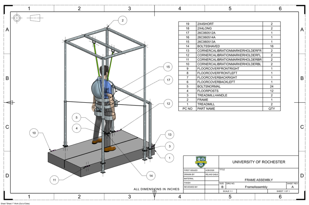
The guide bolts were the team’s solution to the frame alignment issues. These bolts would allow the frame to be mounted and bolted with less effort. To create the guide bolts, ¼ in. (diameter) bolts were modified so that the holes in the frame (that would match the holes in the mounting plates) could easily slide into the bolts. Using the belt sander, about ¼ in. of the bolt length was shaped into a cone. The result was a bolt with a point at the threaded end (opposite the end with the bolt head). This would help the frame slide into place easily. Only two out of the four holes on each mounting plate had guide bolts screwed in. The other two holes were used to bolt the frame down. Additionally, floor covers were manufactured to prevent anyone in the space from stepping directly on the exposed bolts and injuring themselves.
Floor Covers
The holes in the floor and spiked guide bolts create a hazard for anyone in the space. The solution to this was to create floor covers out of plywood. The holes in the floor were measured, and plywood was cut accordingly to fit the hole. The table saw was used to cut the plywood into the shape of the hole. Holes were then cut into the floor covers to fit the guide bolts. A handheld drill with a ½ in. bit was used to create these holes. The rectangular hole in the middle of the floor covers is used as a handle to pick up the covers when the frame needs to be set in place. A handheld drill was used to make holes where the four corners of the rectangle would be, and a handheld jigsaw was used to cut out the rest of the rectangle.
Grommets
To create the integrated harness, customized to the needs of the Motion Lab, grommets were implemented to organize wiring. Two grommets on both sides (four grommets total for this application) of the pouch were implemented so the load cell wiring could pass in/out of the pouch without having to go through the zippered opening. Four grommets were implemented between the front and main pouch so that the amplifier wires could connect to the NI DAQ device. The NI DAQ device was placed in the front pocket, whereas the amplifiers were placed in the main pocket. During this process, a small hole was punched into the harness using a hole puncher provided by the kit, and grommets were clamped together on the hole by a grommet tool provided in the kit.
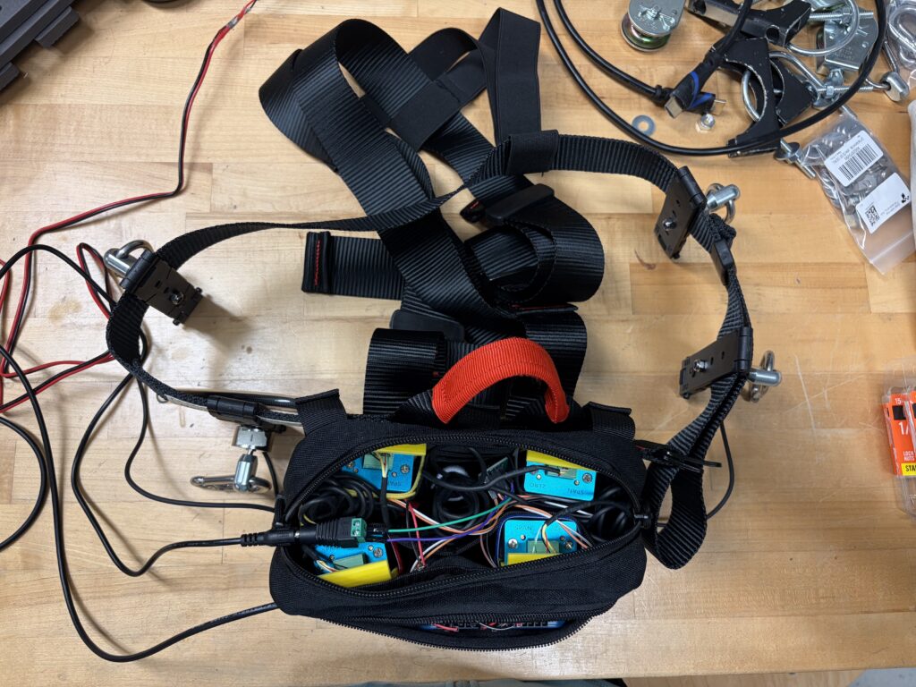
Wiring and Cable Management
Ensuring that all cables and wires were dressed and organized well was necessary to ensure the success of the project. Most of the wiring to the load cell amplifiers and NI DAQ device were placed into the harness pouch to prevent these fragile wires from encountering tension, when the paracords connected to the patient were pulled on. Because the inside of the pouch is smaller than anticipated, the wires fill almost all the space inside, but are color coded to each respective load cell and amplifier to avoid confusion. Initially, the connection to the 10V power supply used two banana cables, resulting in unnecessary extra wires inside of the pouch. However, the team was able to resolve this issue by replacing the banana cables with a breadboard where wires were soldered to prevent the wires from coming loose. Moreover, the team also manually extended the wire of the 10V power supply so that the barrel connector could reach the newly soldered breadboard, which connects to the load cells. The Motion Lab originally had set the wiring up in a way that the banana cables would have had to go inside of the harness. Instead, extending the wire and utilizing a breadboard inside the harness pouch allowed for more flexibility in how things were arranged.
Design Day Frame
Frame Tubing
The Design Day frame was created using extra aluminum piping from the Motion Lab. The piping was cut into three three-foot tubes, two four-foot tubes, and four seven-foot tubes, using horizontal band saw. The Motion Lab also provided T-joints and four-way joints to connect the tubes together, and feet to bolt the frame to the sheet of plywood. Once the tubes were in place, a 3/16 in. Allen wrench was used to screw and secure the tubes in place.
Plywood
To prevent the Design Day frame from moving when someone is hanging from it, the frame was bolted onto a 5 ft. x 4 ft. piece of plywood, which was cut to size using a table saw. A handheld drill with a 1/4 in. bit was used to create the four holes for each of the four poles on the Design Day frame. 1/4-20 in. bolts were then used to bolt down the Design Day frame to the plywood sheet.
CAD Assembly
MATLAB
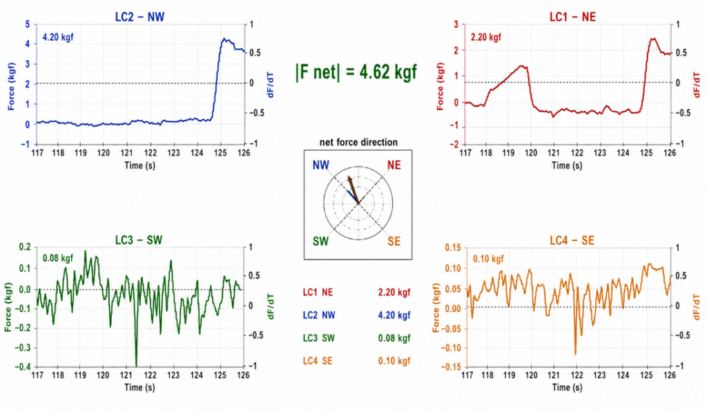
The integrated harness was also tested with the MATLAB code provided by the Motion Lab. This was to make sure that everything was hooked up properly and was providing the correct data that the Motion Lab will need to use. Additionally, the code was modified for the Design Day exhibition. Each load cell corresponds to a force graph and then the figure in the middle is an arrow that rotates and grows depending on which load cell is being pulled.
Future Work
Given more time, further implementation of VR, including motion tracker markers on the feet, would be a priority. Currently, the Motion Lab uses motion trackers in conjunction with force plates to assess how a patient’s foot lands when their gait is disturbed. The Motion Lab could further immerse the patient by providing an environment with obstacles in VR that could track the patient’s full-body movement. If there had been room for cameras, access to Motion Lab’s motion trackers, and more time, this could have been implemented on Design Day.
The guide bolts solution to the frame alignment, as decided by the team, currently solves the problem at hand, allowing the frame to line up with the mounting plates easier. However, an even more efficient solution could be implemented, since the frame alignment with the guide bolts takes at least five minutes with two people. See Figure 10 for other solutions to the frame alignment issue, which could have been implemented with more time on the project.
Additionally, the cable management inside the fanny pack on the harness could be improved. The fanny pack implemented was one that would not be too bulky on the patient, have loops that can easily be attached/unattached, and have multiple pockets, as requested by the Motion Lab. However, due to fanny pack’s smaller size, the wires intended to be neatly packaged into the fanny pack are packed tight, without much empty space, to ensure that the fanny pack can zip closed. The wires and load cells are color coded to prevent further confusion, but to perfect the packaging, the wires and amplifiers should have more room to ensure that wiring is clear.
Acknowledgements
UR Medicine Motion Lab – Zachary Farnam, Dr. Ram Haddas, Dr. Ronald Wood, and Brian Morey
University of Rochester Mechanical Engineering Dept. – Professor Chris Muir, Jim Alkins, Chris Pratt, Sam Kriegsman, and Elizabeth Martin