
Team Members
- Ali Mganga
- Cristian Ramos-Luna
- Jason Kahn
- Vision Aryal
Sponsor

Project Overview
Project Description
NASA brainstorms ideas for potential rovers on other planets, because each planet has a unique terrain. These designs present solutions that are specially adapted for particular environments. Previously, rolling robots manipulated their center of mass to invoke rolling motion. We have designed and manufactured a robot that deploys linear actuators to invoke a rolling motion to navigate flat environments.

Observations & Shortcomings
- Current methods of locomotion face difficulties with certain obstacle
- Rolling locomotion can allow for more precise movements around and/or over obstacles
- Previous rolling robots manipulated their center of mass to create motion. Limited acceleration is produced from this method
Opportunities & Gaps
- Omnidirectional movement
- The proposed technology is relevant to current engineering problems
Requirement/Specification/Deliverables
Deliverables
- Prototype robot
- Written report
- Theory of operation manual
Initial Requirments
- Locomotion of the robot should be novel
- The chassis shape will be a regular geometric object
- Actuators that allow pivoting on sides.
- Power source inside chassis (non-Tethered)
Initial Specifications
- Cost no more than $1000
- Robot no larger than 4 feet
- Inside volume no smaller than 8” x 11” x 14” – electrical equipment
- Chassis weighs no more than 40lbf
- The Center of gravity stays within 0.5” when rolling
- Worst case floor angle of 20 degrees
Concept of Project
Geometry of Chassis


Multiple concepts were considered during the initial stage of chassis development. The team decided to stick to a semi-symmetrical shape. The 4 shapes that were considered are displayed above. The prototyping of each of the shapes was made from cardboard, which allowed us to quickly simulate and understand the feasibility of each shape’s movement and shortcoming.
A Pugh matrix was created to select the most optimal final shape for the chassis. The matrix followed five different criteria which can be seen above. The five criteria are factors that the Mechanical Engineering team and our sponsor foresaw as the most crucial aspects of chassis selection. Design 3 (square – orthobicupola) was initially selected as the optimum design because it met most of the criteria that were set for the robot.
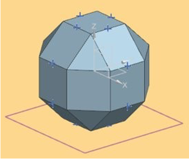
An NX CAD model of design 3 was created to simulate movement and to capture the feasibility of adding actuators to stimulate robot maneuverability. The three possible areas that were considered to place actuators are the faces, edges, and vertices. The team decided to move towards putting the actuators on the edges (over the vertices) because fewer actuators are needed for maneuverability.
A major shortcoming was identified. From a geometry analysis of a hexagon (general profile of design 3), it was found that the actuator length needs to be equal to the radius length of the shape to stimulate robot movement. This is not feasible because the robot will need to house the electrical equipment, leaving no room for actuators to extend all the way to the center of the body. This challenge was addressed by using an octagonal shape. Design 4, a rhombicuboctahedron, follows the profile of an octagon in three directions and is the second-best option in the Pugh matrix. Unfortunately, this shape change increases the number of actuators required from 12 to 16 (more edges than sides). This is a necessary trade-off.
A complete Frankenstein model simulating dynamic movement in all directions was performed in addition to other analyses: A complete breakdown of each analysis can be found below in the Final Design Report attached in the reference section below.
Actuator Development
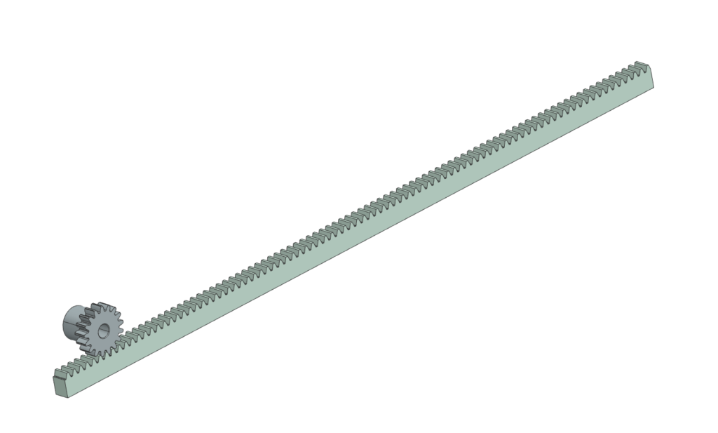
The possible actuator types that were considered were pneumatic and electric actuators. When selecting the actuators, the principal factors that we had to consider especially for the purpose and application of this project were power source and energy, force and strength, load capacity, mounting style, torque, and speed. The team decided to consider mechanical systems that could be used as actuators (rack and pinion and crank and slider). The team selected a Rack and pinion system because it is the most familiar and it has a simple method of creating linear movement.
Material Selection
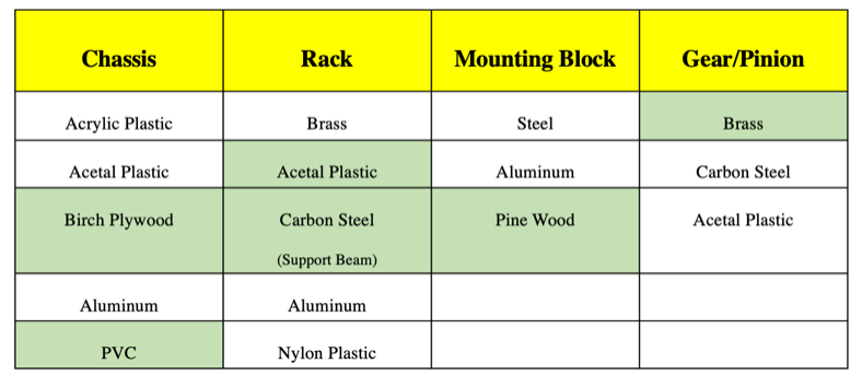
To conclude our selection and conceptual process the team had to select all materials that would be used for the chassis and its components. For the chassis, the team decided to select Birch plywood for the outside robot skeleton and PVC for the edge and side connectors of the different faces. The combination of Birch plywood and PVC gave a unique characteristic to the chassis (ease of manufacturability, strength, stiffness, and rigidity) and support all the stresses that will be occurring during movement. For the rack, acetal plastic was chosen for its low cost. However, steel reinforcement is required for structural integrity. Finally, for the motor assembly mounting blocks, softwood was chosen as it can easily be worked with. All material selections for chassis, rack, mounting block, and pinion can be found in the charts above.
Mechanical Analysis
Chassis Static Analysis


- First image – Free Body Diagram of the robot at start of movement.
- Second image – Free Body Diagram of the robot at a tipping point
- Third image – General Equations
Various stress analysis was done using finite element modeling and simulation to determine what type of rack was required. Plastic racks are more suitable for the budget, so the analysis was performed on an acetal plastic material. A few different loading cases were performed on the rack to observe whether the plastic will yield during the actuator’s movement.
Static analysis was performed for the case of initial movement and at tipping. Analysis, calculations, and equations used can be found above. More details on calculations for each case as well as other analyses can be found below in the Final Design Report in the reference section below.
Rack and Pinion Analysis

To check if the acetal rack will not yield during extension, equation 3 was used for a chosen actuator extension case of 1 inch. The above FEA analysis was produced. Since the max stress is around 9800 psi which is well over the 8630 psi yield stress for acetal and plastic racks are quite inexpensive, methods of reinforcement were investigated. 1005 steel beam of 3/16” x 3/16” cross-section was used for reinforcement. This reinforcement method solved our structural issue.
Simulations
Manufacturing and Assembly
Actuator

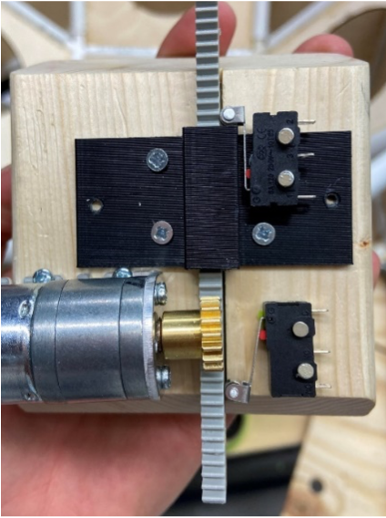
The actuator assemblies consisted of 8 major parts (excluding screws) which can be seen above. Of the components that make up the assembly: parts 1, 3, 4, 6, and 8 were purchased and parts 2, 5, and 7 were manufactured.
The mounting block is the main foundation of this assembly. Wood became the chosen material for the mounting blocks and although wood has some variability in size and flatness, as well as a higher friction coefficient than plastic, its ease of manufacturing was favored. To limit the effects of friction, since the rack will be sliding along the wood, wax is used and added to the surface.
A 2in x 4in x 8ft whitewood stud was used to cut into 16 identical blocks. The mounting block has a cut at an angle of 67.5 degrees. A miter saw was set up using the complementary angle of 22.5° and calipers were used to section the wood into 3.5-inch pieces. A table saw was used to create a slit along the block to allow the rack and steel bar assembly to slide through. A table saw was used to cut off the corner of the mounting block so the rack could line up with the middle of the PVC edge. This entire process was repeated 16 times for each mounting block.
Chassis


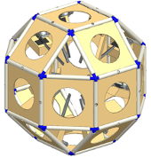
The main body of the robot is made of 1/8” plywood for the faces (1), ½” PVC for the edges (2), and 3D printed joints made of ABS plastic (3). Manufacturing of the frame involved repeated processes of cutting, milling, printing, and assembly.
The faces are made of 1/8” birch plywood because it is lightweight and can easily be fabricated using a laser cutter. These faces were a little less than 10 inches in length on either side and had a slot pattern along the edges. Most of the faces had a 6” diameter hole cut in the middle to reduce weight and allow for ease of access inside the robot once assembled.
The PVC was used primarily to mount the plywood panels at specific angles relative to one another. The PVC was cut and placed in the mill to size. A fixture was designed to set the PVC at the correct angle of 135 degrees. Additionally, 16 of the 9” sections were drilled through the middle of the PVC to give clearance for the actuator to pass through.
The corner joints were developed from a geometrical analysis of a wireframe model of the chassis using NX. Twenty-four of these corner joints were 3D printed with an ABS filament.
Once all the components were manufactured, the chassis was put together using a two-part epoxy.
Testing & Adjustments
The motors were tested to see if they were capable of lifting 35lbs. This showed a significant force being placed on the motor. A bracket was designed to constrain the rack and reduce the force on the motors.

Once assembled, all 16 actuators were tested using an electrical power source to verify that the robot would roll over when the actuators were extended.

Further testing was performed to evaluate each specification:
- Balancing robot on PVC pipe to determine the center of mass
- Used scale to determine the weight of the robot
- Used tape measure to determine dimensions
More details on testing of requirements and specifications as well as all other testings can be found below in the Final Design Report attached in the reference section below.
Electrical Components
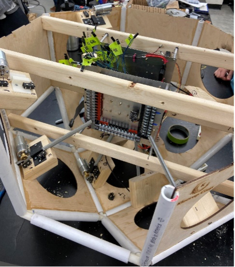
The electrical equipment is mounted primarily to the four support beams that span across the center of the robot. The electrical equipment is made up of two panels with standoffs on each corner. The standoffs connect to the support beams. The panels have wiring connected to all of the motors, limit switches, and other electrical equipment scattered along with the chassis. This equipment consists of stop buttons and ultra-wideband boards.
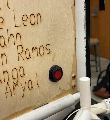
Four stop buttons are positioned around the chassis of the robot. Placed on the three solid panels and one of the hole panels, these buttons are scattered evenly around the robot. If for any reason the robot needs to be stopped during its movement, these buttons should be pressed. There is a light in the button that corresponds to off / on.
NMR Robot 2D Drawings
Final Design Report
NMR Theory of Operation Manuel
Acknowledgments
Electrical Engineering Team
- Jack Bell
- Alex Kleerup
- Eric Elias
- Theodore Leon
Professors and Staff Members
- Dr. Christopher Muir, Department of Mechanical Engineering
- Dr. John Lambropoulos, Department of Mechanical Engineering
- Professor Jack Motley, Department of Electrical Engineering
- Jim Alkins, Rettner Shop Manager
- Anna Remus, Project Leader
- Alexandra Ferrarese, Staff Accountant
Reference Links
- FDR (Final Design Report)
- Theory of Operation Manuel
- PDR (Preliminary Design Report)
- Electrical Engineering Project Overview
- Robot 2D Drawings
- NMR CPM (Critical Path Method)
- NMR BOM (Bill of Matierals)
Meet The Team

Ali Mganga
Ali is originally from Kenya and has lived in Pittsburgh since moving to the United States. He enjoys reading and watching documentaries on WWII and learning about military history. In July, Ali will be joining Accenture in their Consulting Development Program as a Technical Consulting Analyst.

Cristian Ramos-Luna
Cris is from Brooklyn, NY. In his free time, he enjoys lifting weights and collecting sneakers. In June, Cris will be joining the Boeing Commercial Airplanes Engineering Team as a Multidisciplinary Engineer.

Jason Kahn
Jason is from Annapolis, MD. He enjoys spending time on the water in the summer and skiing in the winter. In August, Jason will be joining the Mechanical Systems department at Northrop Grumman’s Space Systems working on satellites.

Vision Aryal
Vision is from Nepal. He loves spending time playing games. Vision will be finishing his degree this December. He aspires to help thousands of people.